

Latest News
November 1, 2012
By Kenneth Wong
If you’re involved in analysis, you’re already engaged in design optimization. After all, the reason you’re running stress analysis on your computer chassis is to identify the right thickness for its walls. If you overdesign it to beef up durability, you add weight to the unit, making it cumbersome to deploy and operate. If you skimp on material, the unit breaks at the first accidental collision with a hard surface. The search for the correct thickness is, in a manner of speaking, the quest for optimal design.
The current process is to build the geometry, analyze it, refine the geometry, analyze it again “and it goes on until the designers and engineers are satisfied that they’ve reached the best design. But a new, emerging workflow could replace the current cycle with a shorter one, by relying on the software to identify the best shape for your design. Altair Engineering’s SolidThinking Inspire, a companion to SolidThinking Evolve (reviewed in DE’s October issue), exemplifies such a workflow.
Modeling Tools
Whereas SolidThinking Evolve is a non-uniform rational basis spline (NURBS) modeler intended for building complex surfaces using splines, SolidThinking Inspire aims to help you analyze your design and identify the best possible shape, based on your design criteria. (Author’s note: For this review, Inspire 9.0 Beta code was used.) That doesn’t mean Inspire is completely devoid of modeling tools, however. It comes with a collection of 2D sketching and 3D modeling commands.
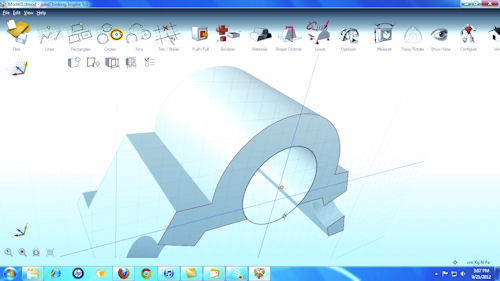 |
| Altair Engineering’s Inspire comes with some modeling and sketching tools, but its primary aim is design optimization. |
In 2D, the lines and arcs behave as they should in top-of-the-line parametric drafting programs. When you move your center points and connected corners in the drawing, you’ll notice that nearby elements adjust themselves to preserve their parametric relationships with the changing geometry. In 3D modeling, you build geometry mostly through Boolean operations and extrusions. Though they’re not as comprehensive as the modeling tools you’d find in a standard mechanical CAD modeler, Inspire’s tools are sufficient for creating shapes to represent a design’s geometric volume, or to prepare imported models for optimization.
To those unfamiliar with it, optimization may seem like a mystical art practiced by digital alchemists. But Inspire simplifies the process to the point where it’s much easier than, say, a typical computational fluid dynamics (CFD) job. The optimization process begins just like an analysis session. You open your design, isolate the region you’d like to study, and specify the material.
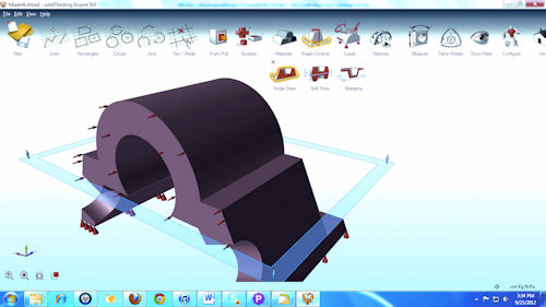 |
| The optimization process is similar to analysis. Required inputs include loads, pressures and fixtures. The extra step is specifying a draw direction, as shown here. |
The preloaded material database in Inspire 9.0 Beta is limited. Andrew Bartels, Altair’s program manager for Inspire, explains: “We’ll add a few more ]material types] before we release 9.0, including a few plastics. If a material you’d like to use isn’t listed, it is easy to add it to Inspire by selecting the My Materials tab on the Parts and Materials dialog. We only require E, Nu and Rho of the material. If your model is completely made out of plastic or steel or aluminum, it doesn’t really matter what material you use for the optimization as the load paths won’t change. If you have steel bosses in plastic parts, it is important to understand your materials, as the load paths will change between the two dissimilar materials.”
The Draw Directions & Shape Controls
One step required for Inspire’s optimization that you don’t need in analysis is specifying a draw direction. Simply put, the draw direction defines the manner in which your part will be built. For example, for a part intended to be injection-molded in two halves, you’d use a split draw direction with a plane located at the center. A part to be built by stamping, on the other hand, requires a different type of draw direction. The draw direction affects how the software calculates the optimized shape, so the result displayed is different when you alter the draw direction.
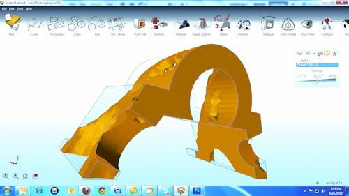 |
| The optimization results show where you should add more material, and where you may trim to counteract the concentration of loads. |
If you don’t specify any shape control preferences, Inspire shows results based on the exact distribution of forces. This often produces a shape that’s asymmetrical. Because most manufactured designs contain symmetry (both for aesthetics as well as easy production), you may specify if you’d like Inspire to mediate the results into symmetrical features.
Time to Optimize
The remaining steps in optimization with Inspire are almost identical to typical steps analysis. You specify loads, pressures and torques on surfaces where you want to simulate impact or forces. Then you specify the surfaces or points where you expect the part to be fixed or mounted. Once these inputs are in order, you have all the essentials for an optimization study.
The optimization dialog box gives you a way to choose your target mass reduction by percentages. This allows you to consider, for instance, how you might redesign a mounting bracket or chassis with 30% less material. In many cases, weight or mass is a critical consideration for optimization, as lowering weight can reduce cost in material acquisition, manufacturing and transportation.
Once completed, Inspire reveals where you should place a concentration of materials to counteract the loads and stresses you’ve specified. This optimized shape (which can resemble a mesh model of an earthquake-ravaged region) serves as guidance for you to refine your geometry.
You can view the results as a mesh model overlaid on a transparent model of your original design, which gives you clear guidance on where to trim materials and where to reinforce. The interactive display allows you to use a drag bar to see a possible material reduction strategy in increments. The results can be exported directly to Evolve for model refinement, or exported as a mesh model readable in your preferred CAD program for the same purpose.
Asking Different Questions
Software-driven optimization is certainly not a substitute for good design judgment and engineering instincts. Nevertheless, with increased computing power and sophistication in simulation algorithms, it makes sense to rely on software to do the heaviest number crunching and show you the force distribution in micro details. The software-generated results can shepherd your design toward directions you’ve not considered previously (because some force concentration in asymmetrical designs may not be intuitive); they may also confirm what you’ve always suspected.
Running a stress analysis is, in essence, asking the question “How will my part break?” in a language the computer can understand. By the same token, running optimization amounts to asking “How do I redesign the part so it won’t break?”
Altair Engineering’s Inspire makes it easy not only to ask such questions, but also to understand the answer produced by the computer.
Kenneth Wong is Desktop Engineering’s senior editor and resident blogger. He finds that he produces his optimal writing after a double espresso. You can reach him by visiting his neighborhood Starbucks or by emailing him at [email protected].
MORE INFO
For more information on this topic, visit deskeng.com.
Subscribe to our FREE magazine, FREE email newsletters or both!
Latest News
About the Author
Kenneth Wong is Digital Engineering’s resident blogger and senior editor. Email him at [email protected] or share your thoughts on this article at digitaleng.news/facebook.
Follow DE

