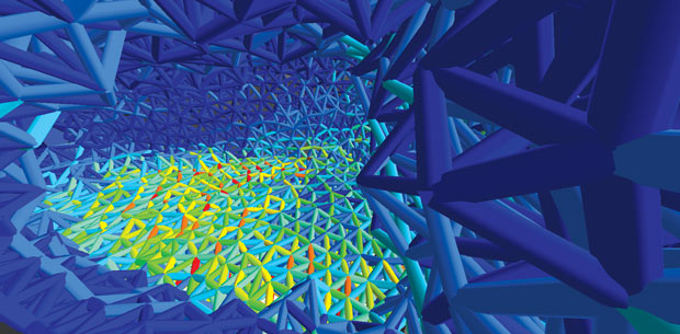
Lattice structure optimization is part of Altair’s OptiStruct solver. In the future, optimization software could offer a hybrid optimization approach, using a mix of optimized solid geometry and lattice structures with varying densities. Image courtesy of Altair.


Latest News
January 1, 2016
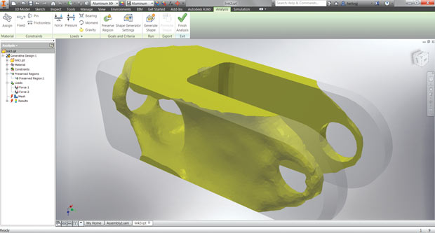 In Autodesk Inventor 2016 R2, Autodesk introduces Shape Generator, a CAD-embedded topology optimization
function. Image courtesy of Autodesk.
For years, design engineers used a mix of vocational training, aesthetic preferences and professional know-how to generate early concepts for a product. Then, these ideas were put through digital simulation and physical tests to identify the most promising candidates. But the advent of topology optimization turns this workflow on its head.
Using stress, load, material and other boundary conditions as input, the engineer can (in a manner of speaking) ask the optimization software to mathematically compute and generate the optimal shape. The role of the software is fundamentally changed, from a mindless geometry-sculpting tool to a design engine with its own modeling logic. From time to time, even experienced designers are surprised by the elegance, simplicity or sophistication of the so-called optimized shape proposed by the software.
Previously, the designer’s job was to conceive and perfect the product’s shape. With topology optimization, they must learn to shepherd the computer-aided shape exploration process instead. It’s a new way of using software. In fact, the verb “use” is not quite accurate here. From now on, the conceptual design phase will be driven by a partnership between human intellect and programming code, between the designer and his or her software.
Trimming Fat and Growing Bones
Under the hood, topology optimization software uses the same principles—and often the same solvers—found in finite element analysis (FEA) and simulation software. For instance, Autodesk’s Shape Generator feature in Autodesk Inventor 2016 R2 (released October 2015) relies on Autodesk’s Nastran FEA solver. solidThinking Inspire, an optimization package from Altair, uses Altair’s OptiStruct solver, also found in the company’s higher-end HyperWorks software suite.
Generally, this is the software-driven optimization workflow: (1) The software runs FEA to identify the stress and load concentration in “the design space,” the region designated as the boundary for shape exploration; (2) it derives a new (lighter) shape by removing materials in the areas unaffected by stress. In doing so, the software preserves sufficient structural strength to counteract the anticipated load without excess material.In addition to Inventor’s Shape Generator, Autodesk also offers lattice-structure optimization with Autodesk Within, an offspring of the company’s Dreamcatcher research initiative. At a briefing with the media at Autodesk University (AU) 2015, Lance Grow, director of Autodesk’s Product Design Product Line Group, summed up the distinction between the two: “[Autodesk Inventor’s] Shape Generator removes materials from an existing part based on load properties. With Autodesk Within, the software grows materials [to counteract the anticipated load] based on a variety of algorithms.”
The technical terms and industry nomenclature can be confusing, but if you’ll tolerate some butcher shop expressions, look at it this way: Autodesk Inventor’s Shape Generator uses FEA to trim excess fat from your geometry; Autodesk Within uses algorithms to generate the optimal skeleton structure for your product. Both are examples of computation-driven optimization.
A Hybrid Optimization Approach
Manoj Mahendran is an application engineer and support specialist at Phoenix Analysis and Design Technologies (PADT) who produces optimization tutorial videos for his employer’s YouTube channel. PADT uses Genesis software from Vanderplaats Research & Development for optimization. PADT offers engineering, simulation and rapid prototyping services. It’s also a reseller of ANSYS products.
“There’s a significant drive to incorporate lattice structures into optimization, into geometry modeling, because now they can be printed with 3D printers,” says Mahendran. It’s conceivable that, in the not-so-distant future, the two types of optimization—removing excess materials from geometry and generating bone-like structures to add strength—would converge. Such a combination represents the ideal in computation-driven design.
The latest version of Altair’s OptiStruct solver (released in February 2015) includes the ability to automatically generate lattice structures. “In the future, we will have lattice structure in our Inspire software,” says Jaideep Bangal, senior application engineer at Altair’s solidThinking Inspire. This could result in shapes with “some part in lattice, some part in solid, because that’s what the design needs,” he adds.
The Optimal Stage for Optimization
The introduction of optimization raises questions about where in the product development process it belongs. Advocates suggest it should take place early in the design cycle. After all, you do not want to spend too much time and effort refining and testing a non-optimal concept that invites costly revisions.
“[Optimization] is a lot simpler to do in the beginning stage. So if you’re going to optimize an L-shape bracket, just make two square boxes—don’t spend time detailing the model. Chances are, you won’t end up using the same model you started with,” says Mahendran.
The design engineer’s default tool is usually a CAD program. Such programs are the standard tool for sculpting out detailed mechanical parts and assemblies. But in topology optimization, the designer enlists the software’s help to determine the best shape. Therefore, Altair’s Bangal argues: “Topology optimization should take place before the CAD modeling phase.”
 Lattice structure optimization is part of Altair’s OptiStruct solver. In the future, optimization software could offer a
hybrid optimization approach, using a mix of optimized solid geometry and lattice structures with varying densities. Image courtesy of Altair.
Rani Richardson, a CATIA business experience consultant for Dassault Systèmes, points out: “Starting the process with an optimized detail design brings a lot of advantages to the designer, including decreasing the part lifecycle, removing material where it is not needed while retaining restraints like strength or stiffness. Once designed, a variety of functions and constraints are available for static and dynamic problems. [In Dassault Systèmes SIMULIA’s TOSCA software], multiple load cases and nonlinear analysis are supported and manufacturing constraints can be applied, ensuring the part can be fabricated.”
Traditionally, a novelty tool or a new approach is first entrusted to a smaller circle of experts. The technology is recommended for wider adoption only when it reaches maturity, after it has gone through several generations of trials and errors. Yet, Bangal and his colleagues firmly believe topology optimization should be in the hands of design engineers.
“Computational fluid dynamics (CFD) or FEA is very mature as a workflow, but topology optimization is new to design engineers,” says Bangal. The trick is to hide the complexity of topology optimization behind a simple user interfaces. For Bangal and his colleagues, the answer is solidThinking Inspire, a topology optimization package with a low learning curve.
CAD-embedded Optimization
At the present, topology optimization usually takes place in simulation software programs or in special optimization software packages. However, by introducing Shape Generator in its mainstream CAD program Autodesk Inventor, Autodesk has ushered in CAD-embedded optimization.
“Topology optimization has been around, used mainly by the analysts community with CAE tools or special tools. What’s different about [Shape Generator] is that it’s integrated into a mainstream CAD platform. Our approach is to put it in CAD so it can benefit the conceptual design phase,” notes Jonathan den Hartog, product manager for Autodesk Inventor.
FEA was once the restricted domain of simulation software, but over the years, CAD vendors incorporated simple stress analysis tools into the CAD modeling environment. CAD-embedded FEA is now a standard feature in packages like Autodesk Inventor, SOLIDWORKS, Solid Edge and PTC Creo. While sophisticated simulation tasks (for example, dealing with multiphysics phenomena or anisotropic composite materials) are still relegated to specialists using high-end simulation programs, CAD users’ familiarity and comfort with simple (usually linear) stress analysis is growing. The introduction of topology optimization in CAD software could follow the same pattern in the coming years.
In a presentation to the media at AU 2015, David Benjamin, founding principal of The Living, a design studio Autodesk acquired, said: “We’ve been exploring [computation-driven optimization] technology’s role and also talking to engineers. It’s still too early to know what specialty is needed—or not—to use such a tool. But the framework and the specific techniques and the algorithm could be put inside a whole range of software. Some novice users may provide a series of input and let the software suggests some shapes. At the other end of the spectrum, even the most advanced users with great creativity and intuition can still benefit from such a tool.”
The Role of the Coach
Can optimization be self-taught? Can you learn it by diving into the software on your own, the way some learned to swim? It’s possible, but perhaps not the best approach, according to PADT’s Mahendran.
“I feel that the first exploration should be done with an expert looking over the [newbie’s] shoulder,” he says, “People often bite off more than they can chew—or more than the software can chew.” He advises: “Try to crawl before you run. Don’t start off with a million-mesh topology. Try it with first a low-polygon optimization.”
The software tools that target designers and engineers tend to have simpler interfaces with fewer inputs. Still, points out Mahendran: “You’re trying to approximate the real world as much as possible, but in some situations, you have to make assumptions that have tradeoffs.” It’s difficult for a novice user to understand these tradeoffs without an expert’s guidance.
The Cost of Geometry
Traditional manufacturing methods are designed to cut and mold symmetrical, circular and rectangular features. The simpler it is to produce, the less it costs. However, computation-driven geometry often results in organic shapes, involving asymmetrical patterns, uneven corners and fossil-like structures. Such shapes typically cost more to produce using current technologies and materials.
“If a part weighs 50% less, but costs 100% more to manufacturer, is it really helping you? We have solutions that can shave off weight to the decimal point, but that doesn’t mean it’s the right approach for everyone,” notes Mahendran.
solidThinking’s Inspire addresses this dilemma with the option to add manufacturing constraints. By specifying the preferred manufacturing method, an Inspire user can instruct the software to restrict the optimized shape to geometric features compatible with the chosen manufacturing method.
At the present, standard manufacturing procedures—such as machining, injection molding and stamping—still remain the most economic options for large-volume production. However, new additive manufacturing methods—specifically, 3D printers capable of printing in metal—may soon remove the cost associated with shape complexity.
“Before, if the optimized topology is a natural [organic] shape, it cannot be manufactured in injection molding or machining. Now, with 3D printing, you can forget about manufacturing constraints,” says Altair’s Bangal.
This development can have a profound impact on the way our products look. “The cost consideration that works against the optimized shape will eventually go away, because of 3D printing,” says PADT’s Mahendran. “Organic structure in product is something that will come about soon. When metal 3D metal printing becomes accessible to most engineering firms, these shapes will become more widespread.”
However, it’s a mistake to think of topology optimization is a fully automated process that can be delegated to the software. You still need an engineer to intervene and use his or her judgment, especially when it comes to manufacturing.
With CAD software, you use it like a knife or a drill: You decide where to cut and drill; the software does your bidding. With topology optimization, the software is a partner in the decision-making process. You ask the software: “Where should we cut meat to make it lean? Where should we grow bones to make it strong?” The proposed optimal shape sometimes confirms your intuition; other times, it surprises you with a solution you haven’t thought of. It’s beginning to act more like a sentient design collaborator and less like a primitive chiseling tool.
More Info:
Subscribe to our FREE magazine, FREE email newsletters or both!
Latest News
About the Author
Kenneth Wong is Digital Engineering’s resident blogger and senior editor. Email him at [email protected] or share your thoughts on this article at digitaleng.news/facebook.
Follow DE

