Latest News
March 2, 2009
By Pamela J. Waterman
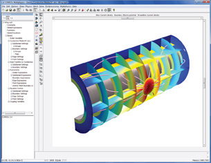 This COMSOL multiphysics simulation illustrates localized heating damage due to lightningstriking a composite-material aircraft wing. Image courtesy COMSOL This COMSOL multiphysics simulation illustrates localized heating damage due to lightningstriking a composite-material aircraft wing. Image courtesy COMSOL |
Although software for composite analysis has been around more than 20 years, you might be tackling your first project that uses this category of materials. Or, your needs in the composite field may have outgrown your current analysis package. Either way, you probably know that dealing with these materials requires capabilities beyond standard modeling and analysis techniques.
The good news is that dozens of companies market software that includes or focuses on using these no-longer-so-exotic materials. The even better news is that these packages work faster with today’s computing platforms, are easier to use than ever, and often connect directly with other vendors’ related offerings.
DE polled the experts to identify the critical issues in evaluating software for composite analysis. They pointed out questions to ask and situations to consider, whether you’re dealing with long-fiber composites, sandwiched layers, or honeycomb structures. The answers are oriented to realworld applications with the goals of durability and manufacturability well in mind. (A resource list at the end of this article includes vendors in composites modeling, analysis, optimization, and manufacturing.)
 Firehole Technologies’ Helius:MCT for Abaqus software shows failureanalysis details of a composite model structure. Image courtesy Firehole Technologies | 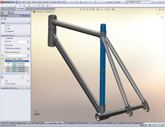 This example within SolidWorks describes detailed composite shell ply definitions to enable a manufacturer of bicycle frames to complete afull-scale analysis. Image courtesy SolidWorks |
Some current goings-on in The composites World Florida State researchers are developing manufacturing techniques that soon may make Buckypaper (layers of a thin-film basically comprising Buckyball carbon nanotubes) competitive with the strongest composite materials now available. Coconut fibers are being tested in place of synthetic fibers to make compressionmolded composites for such automobile parts as bed liners, floorboards, sun visorsand inside door covers. — PJW |
Model Creation
Setting up a composites-based model for finite element analysis (FEA) encompasses the standard steps of defining the geometry, specifying material properties, and meshing the model for analysis. However, working with non-isotropic materials demands that the software lets you define the differing nuances of each layer. Both 3D CAD and analysis packages generally handle this task, but just how they do it, and what else they support, are other points to consider.
- Is the number of possible layers virtuallyunlimited? Some designs may call forten layers, others might require thousands.Advances in computing power have meantthat analysis time is no longer a gating item,so you shouldn’t encounter restrictions inthe modeling.
- Can you import layer data such as strengthand stiffness terms from spreadsheets?
- Can you easily insert or delete layers, andat what points in the process?
- What are the options for defining fiberorientation angles? The software shouldhandle angles with respect to a global axis,local axis, normal to the shell surfaces and aplane defined by two intersecting planes, oralong an arbitrary curve.
- Can you mix composite elements withnoncomposite elements such as beams,springs, and shells made of metallic structures?
- Can you define a layer as a honeycomb, or include rebar material?
- How are glues and adhesives modeledbetween layers—with a surface-based cohesive contact or as a very thin layer?
- Can the design have physical holes? What is the editor like for updating thickness,angles, and material properties? Does the modeling process correspond
to different manufacturing processes suchas hand layup, filament winding, and compressionmolding?
Material Properties
When it comes to defining specific materials, the software should either have its own database or the capability to import material properties data from commercial services such as MatWeb and Matereality.
With that taken care of, ask the vendors these questions:
- Does it allow unit-cell-based micromaterialmodels? Can it also incorporate continuummaterial models? Can it handle a mixof elastic and inelastic materials?
- Can you designate fiber packing as well as braided or woven configurations?
- Can you introduce random variations infiber orientation to allow for manufacturing realities?
- Can you enter equivalent stiffnesses as astarting point, especially early in the design phase, then replace those values on a layer-by-layer basis?
- Does the software allow user-defined equations in the property matrix?
- Is any necessary unit-conversion handledautomatically?
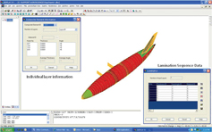 This screenshot illustrates the lamination sequence modeling in NISAsoftware of a composite aircraft model. Image courtesy Cranes Software | 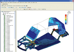 ALGOR is used to analyze a next-gen taxicab frame made of lightweightAlumina composites and carbon fibers. Image courtesy ALGOR |
Meshing
When the model is complete, you need options for directing the meshing (finite element definition) process. Do you want to use solid elements or layered shell elements? Some analysts start by modeling the structure as a layered shell element then switch to a detailed solid element mesh to better understand such results as interlaminar shear stresses. Ask whether such a change can be automatically extracted, especially from mid-planes.
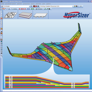 HyperSizer imports finite element models and performs compositespecific stiffened and sandwich-panel failure analyses and layup optimization for lighter weight and manufacturable structures by reducingply drops. Image courtesy Collier Research |
General Analysis
The software should offer both implicit and explicit solvers, and include both macro and micromechanical analyses at: 1) the global level, addressing overall deflection, buckling, and natural frequencies of the structure; 2) the ply or layer level, determining interlaminar shear formations and stresses; and 3) the matrix level, often left out, which supplies a detailed stress distribution within a single layer.
Other questions to ask about the solver:
- To save time, does it use the same FEAmodel for implicit and explicit solutions?
- Can it handle metal-matrix, ceramic-matrix, and polymer-matrix composites?
- Do you have the choice of computingequivalent material properties in either the preprocessor or the solver?
- Do material properties change appropriately with a change in geometry shape?
- Does it account for heat-transfer effects?Can it solve for simultaneous multiphysicsincluding conductivity, thermal, and fluidstructure interactions?
- Can it account for initial strains in the differentcomposite layers (e.g., if a layer is preloadedduring manufacturing)?
And if those tasks aren’t enough, the software should be able to compute out-of-plane (stress z-axis) interlaminar shear and peel stresses. This capability would be in addition to classical lamination theory (CLT) in-plane stresses and strains.
With so much information contained in every square inch of an analyzed composites design, the ability to visualize the details of material orientation becomes critical. Be sure that you can display visual verification of the orientation angles and normals layer by layer; stress results for core, worst, and specified lamina; strain for composite elements including initial, mechanical, and total strain; and damage energy density.
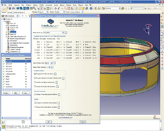
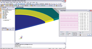 The new Femap 9.3 Layup Editor allows ply properties to be edited individually or collectively. In addition, plies can be rotated or moved around the layup, and users can easily define symmetry for the laminateas a whole. Image courtesy Siemens PLM Software |
Failure Analysis
Composite and laminated materials are subject to failure modes not found in single-material structures. Both delamination (laminate-based failure) and fiber or matrix breakdown (ply-based failure) can degrade performance but the question is, how severely? Will the outer layer wrinkle, crimp, or dimple? Does damage to one layer equate to failure of the entire part? Damage modeling is critical to success.
The software should be able to investigate barely visible impact damage (BVID). Does the software help you define the allowable damage tolerance? Since every designer uses different failure criteria, the package must allow flexibility in the definition, ideally with the option to write your own macros.
If you treat the composite as an equivalent, blended whole, you can examine such values as simple maximum strain and maximum stress, and use quadratic Tsai-Wu, Hill, and Hoffman failure models. Newer criteria account for fiber or matrix failure separately, using such models as Hashin-Fabric, Hashin-Tape, and Puck.
What else should you look at, and how? Some codes provide crush simulation and also use a version of the public-domain VCCT code, a postprocessing and remeshing technique for progressive crack propagation between bonded surfaces. Ask if the failure analysis examines residual strength after first-ply failure, and what approach it takes to do so, e.g., does it use immediate or gradual stiffness reduction for the matrix and fibers? Can you add damage during a simulation (not just calculate it after the simulation)? Can you deactivate elements to simulate material removal or breaking? And can you perform fatigue analysis, a rare capability with composite analysis?
|
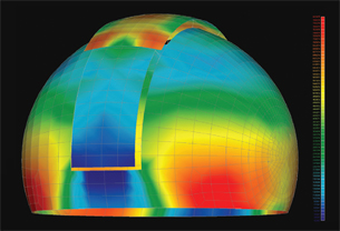 NEi Nastran stress analysis of the radome covering the Southern Astrophysical Research infrared telescope in the Chilean Andes. NEi solved the complete structural analysis. Image courtesy NEi Software
Design Optimization
Typically designers use composite material to minimize weight while meeting performance (strength) requirements. However, the large number of variables involved makes optimization a non-trivial task and can lead to overly conservative designs. Ask about the following points:
- Does the software provide interactiveoptimization capabilitiesso you can determine, for agiven loading environment,the lightest weight combinationof material systems and plylayups?
- How easy is it to reorient layers or changethe stacking sequence to compare behavioraldifferences? Can you quickly change the material type in a layer?
- Can it optimize a complete structural entity such as wings and fuselage of an aircraft?
- Can it handle sandwich structures as well as solid laminate structures?
- Does the package couple with other solvers and pre- and postprocessors as needed?
- Are tolerances in the design parameterstaken into account, and how easy are those to vary?
- Is Design of Experiments a fundamentalpart of the optimization process?
- Can you optimize for an objectivesuch as low vibration, or canyou optimize for multiple objectives?
Manufacturing Issues
Simulation provides great insight but you still need to manufacture a real product. Ask about the interface between the analysis software and the various manufacturing simulation packages. Terms such as draping, taping, braiding, flatpatterns and ply drop-offs should become part of your vocabulary. You also need software that will help you incorporate such non-geometric details as fasteners, glues, sealants, and coatings, and predict any expected thermal warping, shrinkage, and springback.
Composites Resources >A search engine from Firehole Technologies for composite material datasheets. Includes an online, micromechanics-based composite |
The Next Steps
What do the experts see for the future? Software that allows multi-scale analyses, mesh-independent crack growth computations, and more detailed stress distributions within a single layer, to name a few items on the wish lists. For now, view the many good white papers and tutorials at the company websites, talk to the experts about your particular projects, and let their wealth of experience guide you to the “must haves” for composite analysis success.
More Info:
These are companies with software for layered and long-fiber composite analysis and manufacturing. The products include preprocessors, solvers, optimizers, failure
analyzers, material databases, and manufacturing setup planners.
ADINA R&D, Inc.
Watertown, MA
ALGOR, Inc.
Pittsburgh, PA
AlphaSTAR Corp.
Long Beach, CA
Altair Engineering, Inc.
Troy, MI
ANSYS, Inc.
Canonsburg, PA
Collier Research
Newport News, VA
Componeering Inc.
(Convergent Mechanical Solutions)
Seattle, WA
Composite Agency
Amsterdam, the Netherlands
COMSOL
Burlington, MA
Cranes Software
Troy, MI
ESI Group
Huntsville, AL
e-Xtream engineering SA
Louvain-la-Neuve, Belgium
Firehole Technologies, Inc.
Laramie, WY
Lindell
Poquoson, VA
LSTC LS-DYNA
Livermore, CA
Matereality, LLC
Ithaca, NY
Automation Creations, Inc.
Blacksburg, VA
MSC.Software Corp
Santa Ana, CA
NEi Software
Westminster, CA
Peak Composites, Inc.
Arvada, CO
PTC
Waltham, MA
Siemens PLM Solutions
Plano, TX
Simulayt
Brookwood, Woking, UK
SIMULIA
Providence, RI
SolidWorks
Concord, MA
Vanderplaats R&D, Inc.
Novi, MI
VISTA GY, Inc.
Waltham, MA
Contributing Editor Pamela J. Waterman is an electrical engineer and freelance technical writer based in Arizona. You can contact her about this article via email sent to [email protected]
Subscribe to our FREE magazine, FREE email newsletters or both!
Latest News
About the Author
Pamela Waterman worked as Digital Engineering’s contributing editor for two decades. Contact her via .(JavaScript must be enabled to view this email address).
Follow DE