Helping design and engineering professionals discover, evaluate and specify technologies and processes that shorten the design cycle and enable success.

May 2026 Special Focus: Artificial Intelligence in Design and Simulation
In this Special Focus Issue, learn about the latest developments in the integration of artificial intelligence into engineering workflows.

Design & Simulation Software Guide 2025
In this Special Issue, Digital Engineering presents its second annual guide to design and simulation software vendors.
UGS Corp. (Plano, TX) announced Version 9.1 of its pre- and post processing finite element modeling application. Femap 9.1 is, says the company, a key component of the UGS Velocity Series, the company’s new mid-market and preconfigured portfolio of digital product design, analysis, and data management software also just released.
|
|
|
|
|
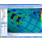
Femap 9.1 from UGS Corp. |
Femap is the FEA (finite element analysis) component of the UGS Velocity Series. It offers in-depth finite element modeling functionality that allows access to advanced analysis solutions in a native Windows environment. Femap is also highly integrated with Nastran, the industry’s leading solver technology, to form a broad and comprehensive CAE solution. A newly established Femap Express is integrated in Solid Edge Version 18 for fast, yet accurate analysis.
Among the enhancements in Femap Version 9.1 are a fully associative interface with Solid Edge V18 for effective geometry transfer in preparation for analysis as well as for maintaining data integrity between design and analysis. A new direct CATIA V5 translator enhances geometry transfer for CATIA users and strengthens Femap's MCAD integration capabilities, which already include CATIA V4, Pro/Engineer, SolidWorks, STEP, IGES, and any Parasolid or ACIS geometry.
|
|
|
|
|
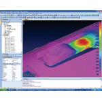
Femap 9.1 from UGS Corp
|
Femap Version 9.1 comes with a fully integrated BASIC development environment, providing direct access to the OLE/ COM API of Femap, as well any other OLE/ COM-compliant application. There's also an updated macro-driven program file environment, with its own access window, which provides recording, editing, and playback functionality for the automation of repetitive tasks.
Other improvements include better mesh quality around critical boundaries and stress raisers with a new quadrilateral element meshing option. Results visualization and collaboration has been enhanced with a new option to directly output JT files. Femap Version 9.1 also supports Nastran spot weld elements, and it offers strengthened NX Nastran integration with a new linear surface–to-surface contact capability.
The first user shipments of Femap Version 9.1 are planned for the end of 2005. For more, click here.
Version 7.0 extends GAUSS with more than 30 new functions.
Aptech Systems (Maple Valley, WA) has released version 7.0 of its GAUSS Mathematical and Statistical System. GAUSS, which is suitable for tasks ranging from basic statistical analysis to solving real-world optimization and data analysis problems of exceptionally large scale, is built around a powerful and flexible matrix programming language. Aptech has advanced its core functionality with a variety of new and improved statistical, mathematical, and matrix handling routines. In total, more than 30 new functions have been added.
|
|
|
|
|
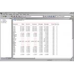
GAUSS 7.0 from Aptech Systems. |
Among the performance enhancements in version 7.0 are Structure Pointers. Structure Pointers allow you to avoid unnecessary data copying when passing structures in and out of procedures, making it possible to write faster programs. A new data set type, GAUSS Data Archives, holds multiple matrices, N-dimensional arrays, strings, and string arrays.
New functions in GAUSS 7.0 include a numerical integration procedure for integrals over infinite intervals and new multivariate normal and students’ cumulative distribution functions. Also provided are three new thread-safe functions and five new functions for creating and opening data files.
Also, GAUSS 7.0 now supports multiple library paths and files larger than 2GB. Its documentation has been redesigned.
GAUSS 7.0, available now, runs on Windows, Linux, Mac, Solaris, and other platforms. For more, click here.
.Net API establishes connection between 3D MCAD and digital simulation
ANSYS Inc. (Canonsburg, PA) has announced the availability of a direct connection between its ANSYS Workbench simulation environment and Designer Modeling 3D MCAD software from CoCreate (Fort Collins , CO). CoCreate's newly available .Net API paved the way for extending the 3D MCAD environment of Designer Modeling to the ANSYS Workbench environment, according to the announcement.
With the integration, solid models created in Designer Modeling can be transferred directly to the ANSYS simulation environment. The integration establishes an association with the 3D MCAD model so that changes made within Designer Modeling are updated in ANSYS Workbench. Also, connectivity between the two applications means that design and simulation can run in parallel.
ANSYS will offer the integration starting with ANSYS 10.0 and version 13.20 of OneSpace Designer Modeling. The Designer Modeling interface is available from ANSYS.
Interactive solver for complex jobs
CHAM (Wimbledon Village, UK) has signed an agreement with UK software developer Symban Power Systems Ltd. (London) to apply and distribute its unstructured APUS-CFD package. APUS-CFD is a fully interactive, Arbitrary Polyhedral Unstructured Solver.
APUS-CFD combines a mesh generation and flow visualization tool. It provides a complete solution from model-building to automatic mesh generation and from parallel and grid computing to real-time visualization in an integrated and interactive environment.
The APUS integrated model builder enables users to build complex models from prebuilt assemblies and imported STL or MCAD files. It generates hexa-dominant meshes from complex geometries automatically.
Users can interact with the system in real time, which allows for changing the solution parameters without stopping the solver. Users can visualize field values (contours and vector displays) while the solution progresses as well as access and post process solution data in various ways, such as contours, vectors, iso-surfaces, streamlines, or XY plotting. Click here for more information.
MicroStripes 7 automatic runs series of simulations that vary design parameters
Version 7 of MicroStripes electromagnetic design software from Flomerics (Southborough, MA) automatically runs a series of simulations while varying one or more design parameter over a user-specified range. Additionally, V7 offers better accuracy of its automatic meshing algorithm, and it enables users to inspect simulation results more quickly by simply running their mouse over the graphical output.
By letting users substitute variables for design parameters, they can model concepts, identify geometric entities as variables, pick upper and lower limits for each variable, and select a step size. MicroStripes then generates as many simulation iterations as required to completely explore the user-defined design space. Each simulation result is plotted on a single graph to quickly determine which parameter values provide optimal performance.
|
|
|
|
|
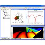
MicroStripes from Flomerics. |
V7’s meshing algorithm is said to mimic what experienced users do as they fine-tune a mesh. This eliminates the need for such fine-tuning and allows automatically generated meshes to be used for most simulations.
Results visualization in V7 has been improved to allow engineers access to the data they need to optimize their design quickly. Running the mouse over a radiation pattern graph, for example, yields the radiation magnitude at each point. Likewise, moving over electromagnetic field output produces field magnitude at a given point. The radiation pattern display has been improved to directly show antenna efficiency and gain. Polarization schemes can now be changed with a single click of the mouse.
MicroStripes uses the Transmission Line Matrix (TLM) method for solving Maxwell's equations. The TLM method when applied to antenna design solves for all frequencies of interest in a single calculation, therefore capturing the full broadband response of a system in one simulation cycle. A further advantage is that the TLM method creates a matrix of equivalent transmission lines and solves for voltage and current on these lines directly. This uses less memory and CPU time than solving for E and H fields on a conventional computational grid.
MicroStripes 7 is available for 64-bit Windows (x64 and Itanium). On these platforms, it comes with a 64-bit solver for problems requiring more than 2GB of memory. Go to the Flomerics home page by clicking here. For detailed information on MicroStripes, click here.

DE's editors contribute news and new product announcements to Digital Engineering. Press releases may be sent to them via [email protected].
Follow DEJoin over 90,000 engineering professionals who get fresh engineering news as soon as it is published.


About Us · Contact Us · Editorial Team · Advertising · Privacy Policy · Subscriber Services · © 2026 Digital Engineering 24/7 · Peerless Media