Picking the Right Output for RE
Knowing what variables to request upfront will save both time and money.


Latest News
May 31, 2009
By Nathan Garrett
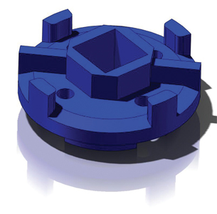 This dumb solid is cheaper than a full parametric model and can be very useful when designing around the part. |
If you called a travel agent and asked for a vacation in a warm climate without giving him an idea of where you want to go and when, you might get a flight to the Sahara Desert on December 25. That’s why most of us communicate our expectations upfront.
The same philosophy should apply when thinking about using reverse engineering for a project. Knowing what variables you need to control and what the end use of the data collected will be is much like giving your travel agent the dates and destinations you desire. The more relative information you give the experts upfront, the better the solution they can provide.
As 3D laser scanning becomes more prevalent, companies need to understand its capabilities to save time and money. Too many times an engineer understands that scanning a part is necessary for a project without fully grasping what results are available to him.
With more than five different outputs available when scanning an object, knowing the ultimate intent of the data will help a professional determine how far to go in the process. Once a part is scanned into an electronic format, translating the data into a useable form is pretty standard regardless of hardware and software. But the further one goes in the process, the higher the cost because each step builds upon the previous step.
Simply scanning an object collects points on an object’s surface and will result in a point cloud representation. From there, a triangulated mesh can be obtained, then a nonuniform rational B-spline (NURBS) surface can be developed, then a dumb solid is created, and finally a parametric model can be realized.
Depending on the requirements of the electronic data, an engineer should be clear and concise about what he needs to help move his project forward and let the laser scanning professionals help with the process. Knowing what variables to request upfront will save both time and money.
Point Cloud
If all you want to do is qualify (to check the quality of a manufactured part against CAD data) a part, then a point cloud is all you are after. Once a point cloud is produced, software such as Geomagic Qualify and Rapidform XOR can be used to fit the data over the CAD data and produce a color map of the deviations. Setting the scale of the color map allows an easy visualization of the quality of the part. You can request a report and the actual point-cloud file. Typically, the companies doing this work offer free viewers for download.
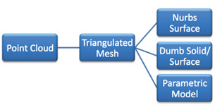 The typical process for developing a laser scan follows these steps: point cloud, triangulated mesh, NURBS surface, dumb solid, and finally a parametric model. |
Triangulated Mesh
The next step in processing scan data is triangulating the points into a mesh shell. This mesh is the same mesh that is output from most CAD software as a .STL file. The mesh is basically a geometric representation of the part created by connecting the dots. A triangular flat surface is then placed between these lines, creating a representation of the part using thousands of triangles.
At this point, if you are looking to have a rapid prototype made, you can cash out. No further processing of the data is needed. Be clear upfront that you intend to have rapid prototypes or a short run of parts made from the scan data. That way, the laser-scanning professional will optimize the data for a quality prototype. Going any further will cost you unnecessary time and money.
NURBS, Dumb, or Parametric?
If you are looking to use the data in a CAD environment, you will need to select one of these types of outputs. Each has its purpose, and depending on which you select, the price tag can be staggeringly different.
A NURBS surface is a set of patches (surfaces) wrapped around the parameter of the part. This representation of the part can be saved out as an IGES file and read into almost any 3D CAD system. This is the least-expensive surface model available. But while it is cheaper up front, this output has many drawbacks and could be costly down the road.
Because NURBS surfacing is generally an automated process, it is very organic in nature and eliminates any corners or sharp features. Experts can optimize the output, but are limited to the organic nature of this type of output.
Because it is a set of many surfaces, these files tend to be larger in nature and do not import as cleanly as a dumb solid or parametric model. Depending on the part, some systems can crash. Also, working inside of a CAD environment with a NURBS model can result in much wasted time, costing you more time and money in the long run.
Because these surfaces are wrapped around the mesh and are organic in nature, they contain no geometric data (i.e., radii, axes, and planes), which could be useful during mating, measuring, and designing. If you are looking to offset surfaces or convert entities, this output is probably not a good choice. Typically, engineers need either a dumb solid or parametric model.
A dumb solid is a geometric representation of the scanned part usually saved out as an .IGS, .STP, or .X_T. This method is better than NURBS, but has a cost associated. This is a manual process. The good thing about this output is that it is cheaper than a full parametric model and is very useful when designing around the part. It gives you actual useable surfaces, radii, axes, and planes. Because this process is more geometric, it typically eliminates any voids, sink marks, etc., and the file is of typical size for normal models, so you will not see a major drop in performance like you would with NURBS patches.
If you have feature recognition software such as Geometric FeatureWorks, a dumb solid could be a good option because FeatureWorks recognizes features and converts them into useable data, allowing you to modify only certain areas of the model. If, like many other engineers, you do not have this resource, asking for the model minus radii or other features can save time and let you apply these features yourself, modifying them at your discretion on your native software.
Parametric Models
Built correctly, a parametric model can harness the design intent of the original designer and should have a full functioning feature tree with no associability to the scan data. These models are built like an engineer would build them.
Be sure to provide a map or photo of critical areas to the scanning pro. Mounting features and machined areas are good indicators of critical areas, but sometimes the intended use of the model dictates other critical areas. So, if you are building a tool to hold a part and need certain organic shapes to hold a tight tolerance, tell the specialist so he or she can select the best approach to recreate that surface.
Be clear about what is important. Should the model be symmetrical or represent a part as-built? Defining what is critical upfront will save unnecessary dialog and modeling.
Defining datums is important to process the part as designed. Depending on the primary, secondary, or tertiary datum selected, the part can be within tolerances and still be out of specification for the design purposes. When possible, provide relevant data such as prints and mating components to help with alignment and checking.
Another aspect to consider when having a part reverse engineered is whether to have the part modeled as scanned or as designed. Many times surfaces are off by fractions of a degree, or cylinders are not truly concentric to each other as exactly as a CAD model can be, so clarifying such areas will help determine the best approach and tools for the optimal output. This is crucial if prints are desired.
Paying for a flight to Fiji when you really just want to drive an RV across the country doesn’t make much sense. Neither is paying for a dumb model when all you need is a triangulated mesh. On the other hand, don’t cut costs on something you do need. Keep an open line of communication with your service provider to stay on time and under budget.
More Info
CRUXTONE
Grand Rapids, MI
Geometric Ltd.
Mumbai, India
Geomagic
Research Triangle Park, NC
INUS Technologies, Inc.
Seoul, South Korea
Nathan Garrett is a design engineer with CRUXTONE Product Development company. To comment on this article, send e-mail to [email protected].
Subscribe to our FREE magazine, FREE email newsletters or both!
Latest News
About the Author
DE’s editors contribute news and new product announcements to Digital Engineering.
Press releases may be sent to them via [email protected].


