Helping design and engineering professionals discover, evaluate and specify technologies and processes that shorten the design cycle and enable success.
Alert!
Digital Engineering ceased publication on July 1, 2026. This website remains available as an archive of engineering content.
For inquiries or information, please email [email protected].


May 2026 Special Focus: Artificial Intelligence in Design and Simulation
In this Special Focus Issue, learn about the latest developments in the integration of artificial intelligence into engineering workflows.

April 2026 Special Focus Issue: Generative Design
In this Special Focus Issue, Digital Engineering takes a look at how generative design solutions can be used across different types of design problems and with a variety of manufacturing approaches to accelerate design space exploration, and…
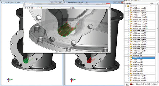
 With the Kubotek Validation Tool, you might discover unintended changes -- in this case, a fillet change -- as a result of translating a CAD file. The top window displays an overlay to help see the difference in better context. Image courtesy of Kubotek.
In November 1999, CADENCE, a trade publication devoted to CAD and product lifecycle management (PLM), published its annual list of Editors’ Choice award winners. In the lineup was 3D Model Server, a web-based model conversion and healing service run by Spatial Inc. Using this portal, you could upload a CAD file in one format and translate it into another format. The product fell into the application service provider (ASP) category. Today, 3D Model Server would have been described as Software-as-a-Service (SaaS) or cloud-hosted.
At the time, home users accessed the Internet via external modems delivering 56K/sec top speed (and bragged about it). Spatial was taking a chance on the CAD users’ willingness to embrace web-based services with its new offering, because it recognized the enormity of the problem it could tackle.
CADENCE Editor-in-Chief Arnie Williams praised 3D Model Server as one of the “trend-setting technologies that will have a profound effect upon the engineering automation industries.” Spatial wrote, “This service is critical to the manufacturing and engineering industries which, to this point, have struggled to maintain interoperability throughout the manufacturing supply chain.”
Spatial, now part of Dassault Systemes, continues to develop and license its modeling kernel to major CAD software vendors. But both CADENCE and 3D Model Server have become extinct. Only ghostly remnants of the editorial recognition and the product still remain online, as archived press releases. However, interoperability -- the struggle associated with managing and reconciling different CAD programs and formats -- is still an issue today.
Paul Brown, Siemens PLM Software’s senior marketing director, said interoperability is “not a dead horse. The horse is very much alive. It’s a horse that’ll continue to live for a long time.” For manufacturing, the use of multiple CAD programs is a fact of life. It’s like a chronic condition: You can’t get rid of it, but you can manage it. Some believe setting up quality control protocols at the point of conversion and translation may be the best approach.
The root cause of interoperability is in the different ways CAD programs generate and edit geometry.
“We have a feature called a hole,” Brown explains, noting that rival company PTC also has a feature called a hole. “The semantics are the same, but the way we draw it, track it and manage the edges is very different from others. Primitive shapes like blocks and cylinders are probably OK [in format conversion], but where you get into trouble is with complex features like blends, rounded edges and freeform shapes.”
Consequently, when you convert one CAD file into another format you’d need to work in -- say, from CATIA to NX or SolidWorks to Inventor -- the resulting geometry may include flaws and imperfections, like gaps, unclosed edges and inverted surfaces. Scott Sweeney, VP of marketing at Kubotek, says, “If they can’t fix them, they’ll redraw from scratch” -- a clue to the kind of CAD rework that adds hours, if not days, to the design cycle.
By virtue of their far-reaching influence, top-tier manufacturers like Airbus, Boeing, GM and Lockheed Martin are well positioned to dictate the formats delivered by their suppliers. After all, they’re the ones offering the contracts and writing the checks. Some manufacturers may dangle a larger paycheck as incentive to obtain the digital design in the format they prefer.
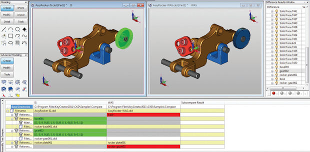
 KeyCreator Direct CAD uncovers a change in an assembly when comparing two versions of a design. Image courtesy of Kubotek.
“I’ve seen it done,” says Brown. “The client may say, ‘If you give me native NX data, I’ll give you more money, but if in neutral or other format, less money.’”
“But most people aren’t Airbus or Boeing,” notes Jim Brown, founder and president of Tech-Clarity, an independent analyst firm. So the interoperability problem travels downstream, to Tier II, Tier III or lower-level suppliers. “From the top, you’ve got big clients saying, ‘You must supply models in this format.’ At the bottom, you’ve got suppliers sending you their work in neutral formats or their own CAD formats. So anybody who’s not a top-tier original equipment manufacturer is going to have to deal with it.”
In the Tech-Clarity white paper “Consolidating CAD: The Benefits of a Unified CAD Strategy,” Jim Brown wrote, “CAD consolidation and standardization have multiple benefits. The first that most think about is cost … More strategic advantages include improved design reuse, collaboration and sharing best practices.” He also acknowledges, “There may be reasons that may prevent companies from fully consolidating their CAD solutions, such as customer mandates to use specific tools. In these cases, a multi-CAD environment is required and must be supported.”
Even if a manufacturer has managed, against great odds, to consolidate and standardize on a single CAD program, Jim Brown points out, “You’re just one acquisition or one new customer away from being back in the multi-CAD environment.”
The emergence of neutral formats -- STL, STEP and IGES, to name but a few -- has helped reduce the headache, to an extent. “Lightweight data is very important,” says Siemens’ Paul Brown. “It’s valid if someone is just designing in the context of the data. Let’s say, you’ve got to design a part that fits inside another piece, you can use the lightweight data.”
Tech-Clarity’s Jim Brown agrees. “You can pull the file into your program using JT,” he offers, referring to a lightweight format created by Siemens, “or some other neutral format. That gives you the geometry, but what if you need to modify it?”
Choosing to work with a neutral format or a lightweight format also means giving up some or all of the part’s geometry construction history -- its parametric formula. The development of direct-editing programs like KeyCreator, SpaceClaim, Autodesk Inventor Fusion, Siemens NX and Solid Edge with Synchronous Technology allows you to edit parts without history.
The vendors’ willingness to grant access to their libraries (often in exchange for licensing fees or royalties) also helps.
“Vendors like Lattice or providers have some kind of capability to read others’ formats,” notes Bill Barnes, general manager of Lattice Technology. “They license libraries to do that. So you’ve got an NX file, you want to bring Inventor parts into it, or something like that, we’ve got these scenarios covered.”
[gallery columns="1" ids="/article/wp-content/uploads/2014/06/import_shelf_modify_1_opt_620.jpeg|,/article/wp-content/uploads/2014/06/import_shelf_modify_en_opt_620.jpeg|The push-pull editing in direct modeling programs, such as Siemens PLM Software’s NX and Solid Edge with Synchronous Technology, helps manufacturers cope with imported geometry because you can edit geometric features without parametric histories. Images courtesy of Siemens."]
Tech-Clarity’s Jim Brown reports that being able to take a file from someone else’s program and read it in your program has evolved for the better over time, but a critical problem remains: “The hardest part is the round trip -- being able to make changes and sending it back to the original author. That’s a long way from being solved.”
Getting all vendors to migrate to a common data model -- the same formula for geometry creation and editing -- is highly unlikely. After all, they’re fierce competitors. But there’s something else that gets in the way. The differences in their modeling formulas also give them the ability to develop unique features that they can claim to be exclusively theirs.
“I don’t think we’ll see all vendors moving to a common data model,” Jim Brown says. “It’ll take away a lot of unique features and innovation they can offer.”
That’s evident in what Lattice has seen among its customers, Barnes says. “Some customers make a conscious decision to use different tools for different parts,” he observes. “One part may be designed with CATIA, another may be with Pro/ENGINEER [rebranded as PTC Creo] or Autodesk Inventor.”
Barnes points out that the old interoperability problem now has a new dimension: interdisciplinary interoperability. “The problem has shifted,” he continues. “As we bring more 3D into downstream usage, we begin to run into interdisciplinary interoperability. You now need to bring electronic CAD (ECAD) and mechanical CAD (MCAD) together, for instance.”
One of Lattice’s clients, for example, ran up against this issue when the company was producing assembly instruction and maintenance manuals. “They had to bring in not only their CAD data for machines, which happens to be in SolidWorks format, but also their wire harnesses and electrical boxes in 2D ECAD formats,” Barnes explains. The customer in question uses Zuken E3, a program that lets you design wire harnesses as 2D layouts but also work in 3D, to consolidate MCAD and ECAD. Electronic CAD software maker Zuken is also an investor in Lattice.
One way to rein in the interoperability issues is to establish good quality control protocols during conversion.
“Check the models before you send them out to make sure the edges and the solids are valid, that there’s no gap,” advises Siemens’ Paul Brown. “If you don’t, you’re just pushing your problem down the line. Someone else will have to deal with the rubbish you sent. Invest in model-checking software to make sure what you’re sending is a valid model.”
Barnes agrees, adding, “If companies are concerned with QA (quality assurance) in data transfer, there are validation tools they should look at.”
Lattice’s translation technology is developed in partnership with Elysium, with a line of product targeting CAD translation and repair. The product’s name alone -- CADdoctor -- is a clear indication that it specializes in healing imperfections. The same product also exists as a plug-in for NX, Siemens’ flagship CAD product.
Another product in the same class comes from Kubotek, best known for its history-free modeler KeyCreator. In late 2011, the company launched KeyCreator Compare, a new product specifically designed to compare and identify the differences among similar CAD files. (Think of it as the 3D CAD equivalent of Microsoft Word’s module for text-document comparison.)
“Companies use KeyCreator Compare to validate that the translation is accurate,” explains Kubotek’s Sweeney. “We have a high tolerance modeler, and we have libraries to read native formats. We have been asked to validate translations between not just different CAD programs, but between different versions of the same CAD program -- CATIA V5 R25 and R26.”
Kubotek also offers Kubotek Validation Tool, described as a product that performs “a mathematical comparison between two similar or different CAD models to ensure data integrity is maintained during a translation or data migration process.” It’s an ideal tool to “ensure that CAD translations have not adversely affected the files or models being translated,” Sweeney says.
During Kubotek’s webinars, Sweeney often polls the attendees to get a snapshot of their CAD setup. “We learn that they have seats of all the CAD software that people are sending them, and they’re supporting all these systems, training them and keeping the software updated,” he reveals.
Lattice’s Barnes also testifies to a similar discovery. “The typical environment with larger customers is, they have a primary CAD tool, but also smaller numbers of seats of other CAD programs that they often receive,” he says.
Juggling multiple CAD programs may seem unavoidable in contract manufacturing, especially among those who work with multiple suppliers and subcontractors. Some may find relief in a CAD system that serves as the primary translator, provided it comes with robust features for reading and writing native CAD files from other programs.
“Many contract manufacturers have reduced their training, maintenance and software costs and saved valuable production time by using KeyCreator Direct CAD as their sole MCAD package for opening, editing and comparing customer files to prepare for manufacturing operations,” notes Sweeney.
Many software vendors recognize they should make a concerted effort to help users cope with the headaches of a multi-CAD environment. After all, their own collective welfare is inseparably linked to it.
As Siemens’ Paul Brown concludes, competing CAD vendors have to coexist: “It’s not in anyone’s interest for any one of us to make it really difficult for our customers to move data around.”

Kenneth Wong is Digital Engineering's resident blogger and senior editor. Email him at [email protected] or share your thoughts or suggestions at digitaleng.news/facebook.
Follow DE


About Us · Contact Us · Editorial Team · Advertising · Privacy Policy · Subscriber Services · © 2026 Digital Engineering 24/7 · Peerless Media