Helping design and engineering professionals discover, evaluate and specify technologies and processes that shorten the design cycle and enable success.
Alert!
Digital Engineering ceased publication on July 1, 2026. This website remains available as an archive of engineering content.
For inquiries or information, please email [email protected].

Digital Engineering April 2026
In the latest issue of Digital Engineering, we take a look at the latest innovations in design for additive manufacturing, including the use of natural language inputs, social media cosplayers, and AI integration. The issue also includes a feature…

January Special Focus Issue: Design for Additive
In this Special Focus Issue of Digital Engineering, learn about the latest advancements in design for additive manufacturing, including new software tools, additive in automotive, custom medical devices, and more.
In this pithy answer Whatmough found a good analogy for the way 3D CAM (computer-aided manufacturing) software works. “The software knows the stock; [it] knows the tool. So it creates toolpaths to cut away the stock until it ends up with your model [the part you’ve designed in CAD],” says Whatmough, Autodesk CAM product manager for the Autodesk Fusion product line.
The description may be simple, but the toolpath programming is not. A novice programmer might not be able to distinguish the areas that require precision and delicacy from those that can be liberally hacked away, thus creating a toolpath strategy that takes much longer. In CAM, longer machine runtime equates to higher cost. Therefore, one of the goals should be to produce the model in the shortest time possible. That skill is outside the realm of some CAD users.
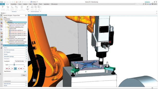 The integrated NX CAD-CAM software lets engineers program robots to perform CNC machining and machine tending using one system. Image courtesy of Siemens PLM Software.
Furthermore, designers who are unfamiliar with manufacturing methods may not be able to recognize features that are costly or impossible to produce. CAD products with built-in manufacturing intelligence, many believe, can prevent the hiccups that tend to occur in the transition from design to manufacturing—from concept to reality.
The need to merge the two independent disciplines (design and manufacturing) and the digital tools that serve them (CAD and CAM) sprung partly from the recognition that many CAD users unfamiliar with manufacturing processes were creating CAD models with characteristics that were impractical or impossible to manufacture.
The logic seems irrefutable. A full set of CAM tools might be overwhelming to the average CAD user; however, a limited set of CAM tools nested within the familiar design software might stop a slew of problematic and unmanufacturable CAD parts from ever being conceived.
“CAD is for creating geometry. CAM is for creating digital manufacturing instructions. In that sense, every CAM tool needs some geometry creation tools. After all, the users need to be able to create toolpaths on the model. And a standalone CAM system is a system with fewer geometry creation features,” Whatmough says.
In 2012, Autodesk acquired HSMWorks, which develops well-known CAM plug-ins compatible with mainstream CAD packages. HSMWorks continues to develop and market the stand-alone products for Dassault Systèmes SOLIDWORKS, a rival product to Autodesk Inventor. But much of HSMWorks’ features have also become part of Autodesk Fusion 360, the cloud-straddling CAD-CAM-CAE package from Autodesk. Autodesk Fusion 360’s CAM functions include 2.5-, 3-, 4- and 5-axis milling, turning with live tooling as well as cutting operations to drive laser, waterjets and plasma cutters.
In 2017, SOLIDWORKS debuted SOLIDWORKS CAM (SW CAM), powered by the technology from HCL. A long-time SOLIDWORKS Gold Partner, HCL is better known for its CAMWorks software, available for integration with SOLIDWORKS and Solid Edge (from Siemens PLM Software).
SWCAM Standard, accessible to those with SOLIDWORKS subscription licenses, supports a 2.5-axis machine. SW CAM Pro, available as an add-on to all desktop versions of SOLIDWORKS, supports 3+2 programming to drive four- or five-axis machines. Whereas SW CAM Standard supports single-part machining, SW CAM Pro supports part and assembly machining.
A good CAD program gives the users a comprehensive set of parametric modeling tools to create any geometry imaginable. But in manufacturing, where the digital CAD models must be made into tangible parts destined for installation in planes, cars and other consumer goods, not all geometry is greeted with the same enthusiasm. Some increase the production cost unnecessarily; others are simply impossible to be machined, cut or molded.
“The milling machine uses a cutter that spins, so it leaves radiuses in pockets and corners,” Whatmough says. Without realizing it, some CAD users might “create sharp corners arbitrarily where they’re not needed. Or they may put a radius that’s far too small.”
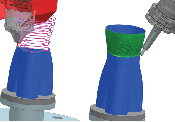
 Hybrid additive manufacturing incorporates 3D printing with CNC machining methods in a single machine. Shown here is how NX CAM software enables users to design parts that leverage both methods. Image courtesy of Siemens PLM Software.
For some CAD users, the choice between a chamfer and a fillet may simply be the preference for sharp edges or rounded edges. But on the shop floor, these choices have financial consequences. “To machine a fillet, you need a specific type of cutter. But if you put a chamfer instead, one tool could be used for a wide variety of chamfers,” Whatmough says.
It’s good to think of CAM software’s simulation capacity in three distinct levels:
1. back plotting, which simulates the tool’s movement along the toolpath;
2. stock removal, which simulates how and where the materials are removed during machining; and
3. kinematic machining, which simulates the machine’s operation.
CAD-integrated CAM products generally target the first two. That is, they let users simulate and visualize the back plotting and stock removal processes. For most parts, these features prove sufficient to catch and fix problematic geometry in the conceptual design phase. Kinematic machine simulation is usually found in dedicated and higher end CAM programs used by manufacturing engineers.
It may also be helpful to divide mainstream and higher end CAM programs into the type of milling operations they support. Mainstream CAM and CAD-integrated CAM programs tend to support 2-, 2.5- or 3-axis operations, which address a majority of the parts made. Higher end CAM programs offer the more complex four- or five-axis machining operations that allow the part to be machined from a greater number of angles and directions.
“It’s easy to simulate where the tool goes, or when it goes where it shouldn’t and crashes. That’s a standard functionality in most CAM software,” says Whatmough. “But simulating to find out whether your fixtures and supports will hold up or not during machining—that’s much more difficult. It’s currently not done.”
SOLIDWORKS CAM uses automatic feature recognition, a strategy much more suitable for those with limited CAM expertise. Mike Buchli, senior product and portfolio manager for SOLIDWORKS CAM, describes it as rule-based machining.
“SW CAM recognizes machine-able features, like pockets, bosses, cuts, holes and contours,” explains Buchli. “Once these features are identified, the software automatically applies suitable tooling strategies based on the size and shape of each feature. The rules come from a database, but they’re also customizable.”
Detailing the features of SOLIDWORKS CAM in a blog post, Buchli writes: “The biggest advantage of Rules-Based Machining for designers and programmers is the ability to read MBD data [manufacturing data] within the SOLIDWORKS part file. SOLIDWORKS CAM will understand the tolerances within a given part file and change machining strategies accordingly ... The process also reduces the chance for error and the possibility of missing a dimension on a traditional drawing.”
Developed by a company with deep roots in manufacturing, Siemens PLM Software’s NX software includes different types of manufacturing checks that you can perform in various phases of your design, according to Vynce Paradise, senior director, advanced part manufacturing, Siemens PLM Software.
“In part design, you can check draft angles, maximum radiuses and use the Synchronous Technology to make geometry adjustments. If you’re the machine programmer, it’s also important for you to visualize the toolpath to see if there could be any clearance problems. At the machine level, you check the G-code [instructions for the machine]. NX includes G-code simulation in the programmer’s environment,” Paradise says. “With NX, you can use templates to predefine the machine or programming methods and apply them to your model. This is important, especially for novice users.”
Vero Software, owned by Hexagon Manufacturing Intelligence, offers PC-based CAD-CAM package VISI, targeting the mold and die industries. “If you have vertical walls in a mold, it’s much more difficult to get the part out of the mold, so you need to add draft angles,” says Steve Sivitter, CEO of Vero Software. “And in sheet metal bending, if you want a 90° bend, you need to bend a bit more to account for the spring-back effect.”
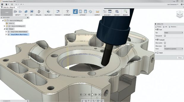 Fusion 360 combines industrial and mechanical design, simulation, collaboration and machining in an integrated concept-to-production toolset. Image courtesy of Autodesk.
VISI includes automatic draft angle analysis and spring-back remedies in the software, Sivitter says. The software can correctly predict such manufacturing idiosyncrasies and recommend fixes because CAD and CAM are tightly interwoven in the same program. In a CAD package developed for design creation exclusively, “the software may not care or have any concern about whether you can actually make your part, or how you could redesign it to make it manufacturable,” he adds.
VISI remains a standalone CAD-CAM product for its niche. The software can work with CAD files produced in other mainstream CAD programs, but it’s not available as a plug-in, for good reasons. If VISI were to become a plug-in, “it [would] diminish our software’s features and there may also be an additional cost associated with the CAD licenses,” explains Sivitter.
At the present, subtractive manufacturing that uses machine tools and additive manufacturing that uses 3D printers are regarded as two distinct options. The hardware and the software that serve the two are also in their own distinct categories: milling machines and CAM software for subtractive; 3D printers and additive design simulation software (an emerging category) for additive. But the birth of hybrid hardware—machines capable of additive and subtractive operations—suggests the two are converging.
Four years ago, DMG Mori unveiled its first hybrid system, the LASERTEC 65 3D. The company announced it had integrated, “for the first time, additive manufacturing into a high-tech five-axis milling machine. This innovative hybrid-solution combines the flexibility of the laser metal deposition process with the precision of the cutting process and therewith allows additive manufacturing in milling quality.”
Last December at the Additive Manufacturing Americas Conference (Pasadena, CA), CNC machine maker Matsuura’s LUMEX made its U.S. debut. The product line is classified as additive manufacturing CNC milling. The company wrote: “The ability to ‘grow’ a metal component in layers with complex internal features and mill those internal features as the layers are added ... [make] the LUMEX Series machines such a distinctive and remarkable production machine tool.”
“My belief is, convergence is inevitable,” says Whatmough. Buchli agrees. “As technologies advance, there may be cases where you want to print a part in metal and then put it through CNC machine to cut specific areas to a tighter tolerance,” he says.
For CAD and CAM software developers, it’s an opportunity and a challenge. “As we get into 3D printing, we have to create new ways to check geometry, new ways to decompose the part to figure out the build sequence,” says Paradise. “That’s an area that’s still in development.”
With topology optimization paving the way for more complex shapes, machine tool operations with hybrid hardware could also become much more complex. “For a long time, we automate things like feature-based machining—recognizing specific geometric features and being able to suggest specific machining strategies. Now, we’re looking at AI as a way to augment that. We could, for example, use machine learning to study the way NX users program their parts. We could use AI to program for more complex shapes,” adds Paradise.
Digital manufacturing erases time zones and physical boundaries. Parts designed in the U.S. and Europe can be securely transmitted to be molded and machined in Taiwan, Malaysia or Singapore. The data management systems allow contractors and clients to monitor the project phases. Software lets both design and manufacturing to occur virtually in the same environment. These give the illusion of communication. Yet, there’s no substitute for the old-fashioned people-to-people communication.
“With an integrated tool [CAD-CAM], the line between design and manufacturing becomes blurred,” notes Whatmough. “So, if the users are not careful, they could end up with a messy environment where the design files and the manufacturing files are not clearly distinguished.”

Kenneth Wong is Digital Engineering's resident blogger and senior editor. Email him at [email protected] or share your thoughts or suggestions at digitaleng.news/facebook.
Follow DEJoin over 90,000 engineering professionals who get fresh engineering news as soon as it is published.


About Us · Contact Us · Editorial Team · Advertising · Privacy Policy · Subscriber Services · © 2026 Digital Engineering 24/7 · Peerless Media