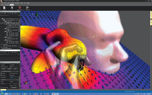
Simulation model of an antenna radiation field from a cell-phone, including influence of fingers. Analysis performed with SPEAG SEMCAD X Matterhorn software. Image courtesy of SPEAG.


Latest News
September 1, 2016
Electromagnetic (EM) design problems used to involve fairly straightforward questions. Will the antenna have sufficient gain and a good beam pattern? Will the motor ramp up to its highest rpm without vibration issues? Does the cable harness need extra shielding? But the ever-present project goals of better/faster/cheaper, combined with the newer demands of higher frequency operation and always-on connectivity require simulation software that handles both fine details and high-level system issues. And there are always the more exotic applications, from lasers and electron beam guns to MEMS (micro-electro-mechanical systems) devices and maglev trains.
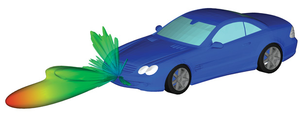
 Propagation paths for automotive, forward-looking radar in an automatic cruise control scenario using WinProp EM simulation software from Altair. The operation is at approximately 76GHz. Image courtesy of Altair.
Good thing there are so many resources to help. Even compared to two years ago (see “Electromagnetic Simulation Collaborations”), EM simulation tools now include more solvers, better meshing techniques, additional materials, easier ways to handle multiphysics and an intense focus on electromagnetic compatibility (EMC) and electromagnetic interference (EMI) concerns.
The (Field) Lines are Blurring

Throwback
While you may concern yourself daily with nuances of timing diagrams, Spice-type simulations, EMI concerns, or parts hunting, changes in the big picture are shining in the spotlight on three broad topics whose effects will indeed filter down to desktop designers:
• Design reuse based on marketable intellectual property (IP) cores
• Collaboration engineering via the Internet
• Co-verification of hardware and software
The three areas are interrelated in a number of ways, but certain companies and aspects stand out in each one.
—“Changing the Way we Design Electronics, Part 1,” DE, September 1998
Designing products with EM functions requires making the device work as specified while minimizing any problems it causes for other parts, systems, devices or people. Larry Williams, director of Product Management at ANSYS, points out that leaving EMI considerations until the tail-end of the design process creates major problems; the entire design process must consider the effects of ground loops and resonances, starting with the smallest interconnect or component on a printed circuit board (PCB).
Nowadays, fortunately, the tools for evaluating EMI and EMC are within most EM software packages, addressing conduction or radiation issues or both. However, for a given frequency range, the applications, goals and necessary simulation capabilities may be more tailored. High-frequency analysis software creates models for strip antennas, parabolic antennas, PCBs, waveguides, radomes and wireless propagation (e.g., through the dielectric bumper of a car, inside a house or across a city). Low-frequency applications include motors, transformers and induction heaters. Electrostatic simulations help with today’s touchscreen devices while magnetohydrodynamics software addresses esoteric plasma containment systems.
General Purpose, Multiphysics EM
Many companies design complex, multi-component systems, from cars to satellites to airplanes. For them, general purpose EM software with multiphysics and multi-domain capabilities may be best, with the former supporting EM/mechanical/thermal/fluid simulations and the latter providing co-simulations of EM with vibration or acoustics. Possibilities in this group include packages from Altair, ANSYS, CD-adapco, Cobham Technical Services, Computer Simulation Technology (CST), COMSOL and Livermore Software Technology Corporation (LSTC).
Over the years, Altair has acquired and integrated a number of EM-related software packages into its HyperWorks product to address broad requirements. HyperWorks now includes FEKO for high-frequency work on antenna design/placement on structures, radar and microstrip. Ulrich Jakobus, Altair vice president for EM Solutions and developer of FEKO, says that to expand the company’s EM capabilities, it has improved the algorithm of the asymptotic ray launching solver, and has also acquired AWE Communications with its WinProp software. With the latter, users will be able to model a car with multiple electronic systems, see the effect on those systems of nearby cars, and evaluate the EM performance of the car in an urban networked environment, for example. At low frequencies Altair also offers Flux for EM/thermal simulations of rotating machines, actuators, transformers, sensors and cables that can be combined with Altair’s OptiStruct for NVH (noise, vibration and harshness) evaluation.
If you’re looking into ANSYS EM simulation tools, you might want to speak to Williams about the various solvers and multiphysics/multi-domain solutions that form the core of ANSYS Workbench, such as ANSYS HFSS, with its new shooting and bouncing ray technology. Williams explains, for example, that ANSYS’ hybrid EM solution techniques—combining finite element methods (FEM) with integral equation (IE) and finite element boundary integral (FEBI) methods—lets users both design an antenna and assess its performance within a radome or on a vehicle. A second major application involves advancements in high-speed chip/package/board analysis supported by the ANSYS Electronic Database that imports smart information about 3D components. It delivers electrical, thermal and structural analysis, even analyzing solder joints for reliability. A third area of expertise and improvement is ANSYS’ approach to designing efficient motors that minimize noise and vibration through better drive-signals. The latter employs a new, 10x-faster, patent-pending simulation technology called Time Decomposition Method (TDM).
 ANSYS HFSS, with its new Shooting and Bouncing Ray technology, is suited for design and simulation of automotive radar systems. Image courtesy of ANSYS.
CD-adapco offers EM capabilities within its multiphysics, multi-domain STAR-CCM+ product, recently brought into the Siemens Simcenter portfolio. Beginning with 2D applications such as for electric machines (ferromagnetic and non-ferromagnetic), with a full range of static, steady-state, transient and sliding motion conditions, the company also added a comparable 3D finite volume formulation for non-ferromagnetic materials. Stefan Holst, CD-adapco application manager, says the latest STAR-CCM+ (v11.04) now offers a 3D finite element formulation that performs steady state and transient analyses on ferromagnetic materials and will soon handle eddy currents and relative motion between EM parts. Analysis of low-frequency conducting EMI is also supported. All of this, combined with CD-adapco’s thermal CFD (computational fluid dynamics) simulations, means that users can thoroughly investigate classic EM designs as well as those involving the flow of a conducting fluid through a magnetic field (magnetostatics and magnetohydrodynamics).
Cobham Technical Services is the developer of OperaFEA, a multiphysics FE suite with modules that analyze systems involving electrostatics, magnetostatics, space charge and low- and high-frequency electromagnetics, coupled to thermal and structural considerations. Design efficiency and automation are key goals across the product line, and recent developments have continued to address them.
“We implemented parallel processing to come to a solution more quickly than before, and are using special elements with reduced dimensionality to cut the number of elements required whilst achieving comparable results to the full 3D elements,” says Nigel Atkinson, business development manager at Cobham.
Two examples he gives are the addition of a Thin Sheet Boundary Condition for modeling of long and thin structures (like the walls of an MRI shield) and the capture of induced eddy currents using a Surface Impedance Boundary Condition that eliminates the need for a fine mesh on the surface of conductive materials. Cobham has also implemented Python so customers can automate design processes, as well as a drag-and-drop interface to eliminate data transfer issues within multiphysics analyses.
CST Studio Suite is the centerpiece of EM simulation products from Computer Simulation Technology (CST). The company is to be acquired by Dassault Systèmes this year. Covering static, low-frequency, microwave and RF cases, the suite includes packages dedicated to PCBs, cable harnesses and EM/circuit co-simulation. Stephen Murray, technical writer at CST, says the fundamental CST solvers are integrated into a single user interface.
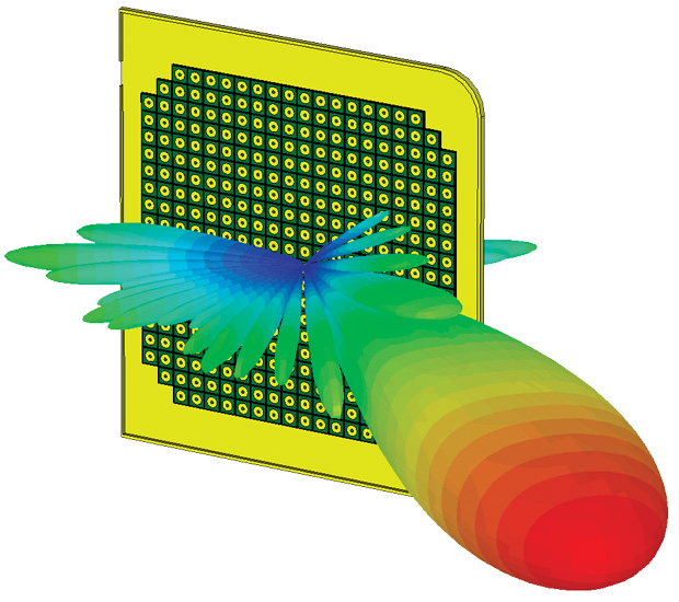 A patch array antenna simulated in fine detail with the CST Transient Solver from Computer Simulation Technology (CST). Image courtesy of CST.
“Users increasingly want to simulate their devices as an integrated system,” Murray says, “rather than as a series of disconnected components. This approach means that after you have set up your model geometry, you can use different solvers for different parts of one application.”
For example, users can simulate an aircraft-mounted antenna using CTS’ general purpose transient solver for the fine details in feeds and radomes then calculate the fields around the whole aircraft using an asymptotic solver; the latter is more efficient for really large objects. To address EMC issues on densely packed PCBs, CST has also strengthened its System Assembly and Modeling (SAM) functionality, enhanced high-performance computing capabilities and added an electronics cooling solver for multiphysics analysis.
Addressing multiphysics from the beginning has been the hallmark of COMSOL software, with new solver technology always in development. That capability is reflected—and being used more often—in each of the COMSOL EM-related add-ons. Magnus Olsson, COMSOL Electromagnetics product manager, sees users placing increasing importance on combining traditional EM with heat transfer, structural deformation and fluid flow.
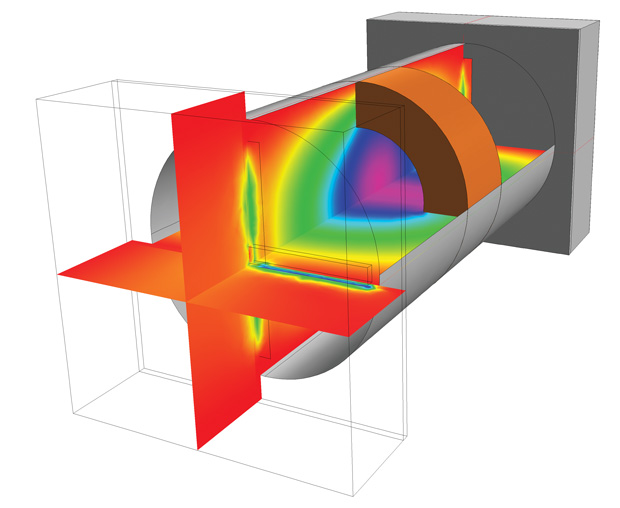 An evanescent-mode cavity filter is modeled in COMSOL Multiphysics. The example is resonant at a frequency lower than its original fundamental mode frequency, and is accomplished by creating an internal discontinuity. Image courtesy of COMSOL.
“One example,” he says, “is our recent addition of methods for combining ray optics with thermal expansion to see how focal points are distorted by thermal effects in laser systems.”
To simplify multiphysics even for non-experts, Olsson says COMSOL also offers a set of preconfigured user interfaces for common physics combinations, such as microwave heating, thermal expansion and swelling in PCBs due to moisture. Low-frequency analysis is covered by the COMSOL AC/DC Module; microwave and RF by the RF Module; full-wave optical phenomena by the Wave Optics Module and very high frequencies or large structures by the Ray Optics Module.
General purpose LS-DYNA FEA (finite element analysis) software from Livermore Software Technology Corporation (LSTC) offers an EM module that supports coupled mechanical/thermal/electromagnetics simulations of systems that operate via current flowing through solid conductors. “The module uses a finite element method (FEM) for the solid, coupled with a Boundary Element Method (BEM) for the surrounding air, avoiding the need to mesh the air and allowing simulations with moving and/or deformable conductors,” says Pierre L’Eplattenier, senior scientist at LSTC.
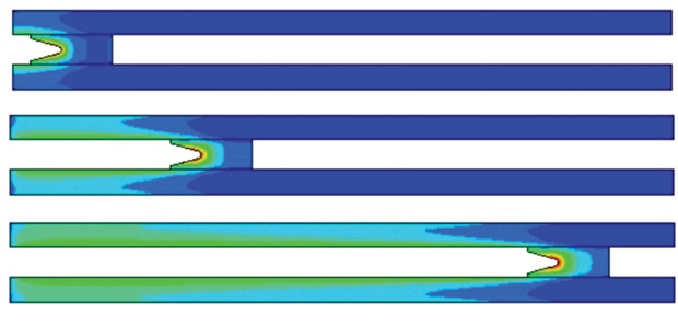 Model of a rail gun as analyzed with LS-DYNA EM module from Livermore Software Technology Corporation. Current flowing between the rails and projectile generates a magnetic field (fringes) and Lorentz forces that accelerate the projectile. Image courtesy of LSTC.
Targeted applications include EM sheet metal forming that can also be coupled with conventional deep-drawing (stamping) processes, as well as magnetic pulse welding, resistive spot welding and complex sliding-contact simulations (e.g., in rail guns). When the EM solver is coupled with LS-DYNA’s CFD solver, users can simulate surprisingly complicated phenomena such as water boiling due to an electric heat source.
Antennas and TX/RX Systems
A specialized EM tool that is just one part of a vast array (no pun intended) of software design products from MathWorks is the company’s Antenna Toolbox. Ken Karnofsky, senior strategist for Signal Processing at MathWorks, says the Antenna Toolbox allows users to design, analyze and visualize antenna elements and arrays with just a few lines of MATLAB code, making it an easy process for experts and non-experts alike. The software uses method of moments (MoM) to calculate such properties as port impedance, current and charge distribution on a surface, and near-field and far-field radiation patterns, in 2D and 3D; the operating frequency range is 10kHz to 200GHz.
“Updates in the latest MathWorks Release (2016a),” explains Karnofsky, “provide more accurate antenna modeling by allowing users to specify the dielectric substrate.” He adds that design results obtained with Antenna Toolbox can be directly integrated in full system-level simulations of the latest multiple-input/multiple-output (MIMO) wireless communication systems and radar.
By acquiring AWR Corp. in 2011, National Instruments (NI) added EM design software for ICs (integrated circuits), packages and modules to its line-up of modular test equipment and LabVIEW software. Now termed the NI AWR Design Environment, this suite includes AXIEM, based on MoM, for 3D planar EM analysis and Analyst, based on full-wave EM techniques, for 3D FEM analysis. A third product, Microwave Office, supports design/layout of RF and microwave circuits ranging from integrated microwave assemblies to monolithic microwave integrated circuits (MMICs). AXIEM can solve 100K or more unknowns in less than 30 minutes per frequency point using fast solver technology and adaptive meshing, according to the company. A quasi-static solver is being added in the next release for more accurate DC solutions. The full AWR Design Environment, according to David Vye, director of Technical Marketing, NI AWR group, “has been developed specifically to address high-frequency electronics primarily used in communications and aerospace applications.” Optional Analyst-MP supports multiphysics analysis of particle accelerators, waveguides, cavities and resonators, and the EM Socket allows easy integration with third-party solvers.
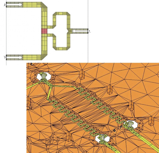 NI’s AWR Design Environment includes AXIEM, a method-of-moments (MoM) solver for 3D planar EM analysis. It meshes conductors only and uses Green’s functions to calculate the effect of conductor currents on each other. Image courtesy of National Instruments.
Remcom focuses on antenna design and analysis. The name of its flagship XFdtd package comes from using a frequency-domain/time-domain (FDTD) approach, particularly effective for simulation of non-linear materials. “Consider a device like a smartphone,” says Jeff Barney, product marketing manager at Remcom. “In order for a simulation to match measured results from a lab, the computer model needs to include all the details. XFdtd includes the phone case, screen, speakers, battery, multi-layer PCB, antennas, etc. We don’t necessarily model the function of all the components (e.g., battery, chips or speaker) but we need to include their physical dimensions and EM properties in order to accurately compute dissipated power and radiated fields.”
Remcom recently released an electrostatic solver for touchscreen design and a Circuit Element Optimizer (CEO) feature for determining which components should be plugged into the matching network layout on the PCB. The latter used to require manual operation and was limited to a dozen permutations. “Now,” says Barney, “XFdtd lets designers run an optimization that considers 10,000-plus combinations in a fraction of the time.”
Though alphabetically toward the end of a list, the Swiss-based company Schmid & Partner Engineering AG (SPEAG) should rank high when you’re evaluating full-wave 3D EM simulation software. SPEAG’s SEMCAD X Matterhorn package handles DC to light applications, including antenna design and optimization, 5G systems, wireless power transfer, microwave and millimeter-wave waveguide devices, EMI/EMC, dosimetry and safety assessments. Combining FDTD, FEM and Mode Matching Technique (MMT) approaches, SEMCAD X Matterhorn offers simulation speed-ups through use of NVIDIA GPUs (graphics processing units) and can run locally or in the cloud. The software features 64-bit kernels and parallelization, and supports a structure-adaptive, sub-gridding scheme for small-featured, non-rectangular volumes. SEMCAD X Matterhorn users who upgrade to the Sim4Life platform from Zurich MedTech AG, have the additional option to investigate multiphysics effects on human models.
The PCB World
It’s hard to think back to a time when integrated circuits were new and printed circuit boards (PCBs) comprised mostly discrete components. But decades ago, software companies were already embracing the power of simulation with innovative products like EEsof, originally developed by HP and improved by current owner Keysight Technologies. The Keysight EEsof EDA software suite supports communications product design with 11 different system-, component- and physics-level design tools. Electromagnetic Professional (EMPro) is a 3D modeling and simulation package for components involving RF and microwave, high-speed digital and RF/mixed-signal ICs. Solvers are based on FDTD, FEM and MoM approaches; electromagnetics and electro-thermal analyses are supported. Applications include cell phones, wireless networks, radar, satellite communications systems and high-speed digital wireline designs.
Another option in this field comes from Mentor Graphics, with its HyperLynx Full-Wave Solver (originally based on the Nimbic nWave product). It solves the full 3D Maxwell equations, without approximations, and covers chip-, package- and board-level simulations from DC to 40+GHz. Andy Haas, product marketing manager for the HyperLynx Full-Wave Solver, says recent updates include improved port modeling, removal of artificial plane resonances, multi-process solver parallelization, accurate volumetric DC solutions for complex low resistance structures (such as 3D analog packages), and true 3D meshing for improved accuracy without large simulation-speed penalties. The package also supports transient and steady-state EMI investigations.
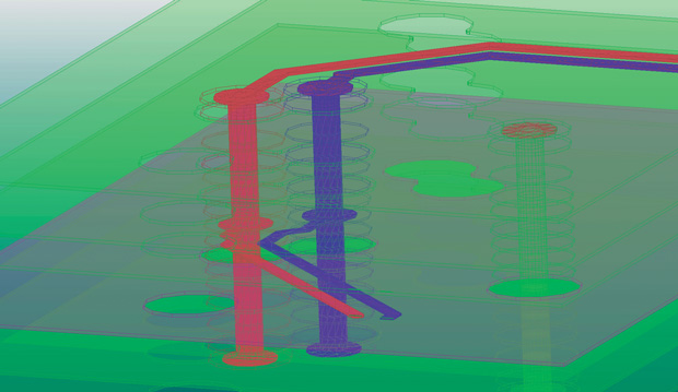 Mentor Graphics HyperLynx Full-wave Solver offers 3D meshing of PCBs, including vias. The company says it eliminates occasional passivity issues and also improves accuracy for complex structures without an appreciable penalty in simulation speed. Image courtesy of Mentor Graphics.
Sonnet Software’s Sonnet suite offers high-frequency 3D planar EM analysis for planar circuits and antennas. Design applications include packaged chips, microstrip, stripline, co-planar waveguide, PCBs (single- and multi-layer) and combinations with vias, metal trace layers and vertical metal sheets in stratified dielectric material. Sonnet uses a highly accurate full-wave MoM approach that incorporates parasitic, cross-coupling, shielding-enclosure and package resonance effects. Considering today’s design challenges, Brian Rautio, lead research engineer at Sonnet, notes that modern circuits are more complex and higher frequency than were imagined even five years ago. “One of the biggest issues that we have found,” he says, “is modeling very thick metals. With the metal aspect ratios being pushed to limits in current designs, loss models are taxed more than ever.” He explains that better loss models were added in Sonnet v16, and improved ones are coming in v17; version 16 also includes an improved dynamic range for port calibrations.
The Low-Frequency Realm
As is the case for many engineering applications, some EM software addresses a more focused set of capabilities via a targeted GUI (graphical user interface).
Infolytica is one such case. Chad Ghalamzan, Infolytica marketing manager, has seen how advancements in high performance computing and cloud resources have made it possible to run simulations that would have been impractical before. But “it’s not just ‘now we can do the same faster,’ it’s ‘what more can we add to the picture’—we see a lot of that,” he says. Infolytica has taken on this challenge by enhancing the physics capabilities of its fundamental 3D simulation packages ElecNet and MagNet; both packages can now link to Infolytica’s ThermNet software, which supports multiphysics thermal analyses. Designers can also now work with MotorSolve, a package that automates the FEA process for designing electric machines.
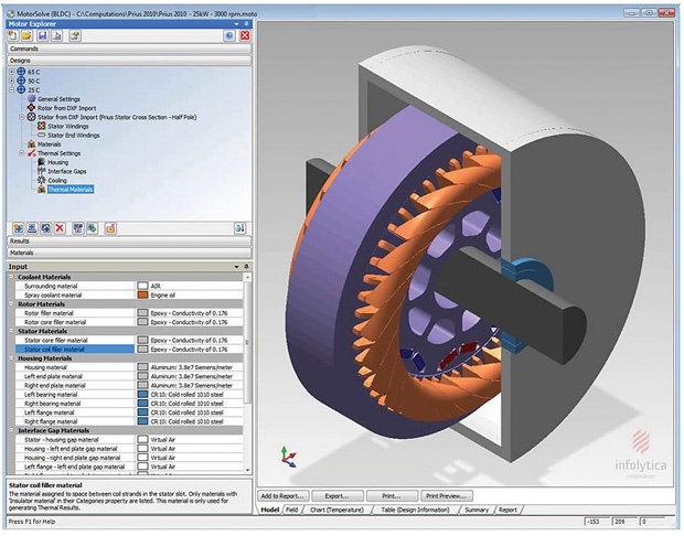 Electromagnetic analysis of a 2010 Toyota Prius 8-pole rotor, 48-slot stator interior permanent magnet (IPM) motor, analyzed with Infolytica MotorSolve simulation software. Image courtesy of Infolytica.
JMAG from JSOL represents another FE analysis software suite designed for low-frequency applications. Its high-speed solvers handle multiphysics effects (magnetics, electrostatics, structural, thermal) as well as multiple domains (NVH and control systems). Automated meshing combined with shared- and distributed-memory parallel processing contributes to extremely fast solution speeds. The extensive suite includes JMAG-Designer (general purpose FEA for EM design), JMAG-Express (a motor design tool) and JMAG for CATIA V5 (EM field analysis embedded in CATIA) as well as a flexible interface to third-party packages.
More Info
Subscribe to our FREE magazine, FREE email newsletters or both!
Latest News
About the Author
Pamela Waterman worked as Digital Engineering’s contributing editor for two decades. Contact her via .(JavaScript must be enabled to view this email address).
Follow DE

