Helping design and engineering professionals discover, evaluate and specify technologies and processes that shorten the design cycle and enable success.


May 2026 Special Focus: Artificial Intelligence in Design and Simulation
In this Special Focus Issue, learn about the latest developments in the integration of artificial intelligence into engineering workflows.

April 2026 Special Focus Issue: Generative Design
In this Special Focus Issue, Digital Engineering takes a look at how generative design solutions can be used across different types of design problems and with a variety of manufacturing approaches to accelerate design space exploration, and…
In 2014 a NASA blue-ribbon panel published “CFD Vision 2030 Study: A Path to Revolutionary Computational Aerosciences,” a paper that continues to be discussed and debated in engineering. “Mesh generation and adaptivity continue to be significant bottlenecks in the CFD (computational fluid dynamics) workflow,” the report summarizes. “Additionally, adaptive mesh techniques offer great potential, but have not seen widespread use due to issues related to software complexity, inadequate error estimation capabilities and complex geometries.”
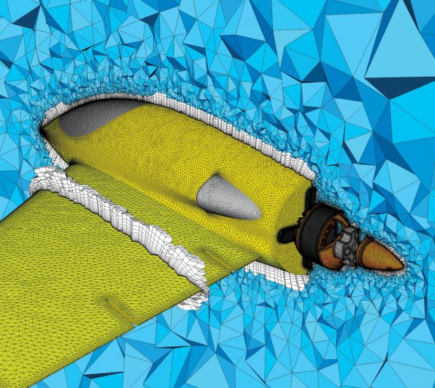 A hybrid prism-tetrahedral mesh for a notional electric-powered aircraft, created in Pointwise. Regular layers of extruded prisms, clustered toward the wall to resolve boundary layers, are displayed in white on the symmetry plane and on a cut through the wing. Image courtesy of Pointwise.
The NASA study notes that in a perfect world the mesh would be invisible to the user. “It is an aspirational goal,” says John Chawner, president and co-founder of Pointwise. “Meshing is completely unglamorous; it is the red-headed stepchild of CAE,” Chawner adds. Engineering software companies “need to take ownership of the citations, where the deficiencies are,” as outlined in the report.
John Parry, electronics industry manager with the Mentor division of Siemens PLM Software, agrees that meshing needs to become mostly invisible as a practical matter. “Meshing is generally a bottleneck for a lot of users. It is not uncommon for CFD users to spend more time meshing than all other things combined, more than 50% of their total effort,” Parry claims.
One problem with improving meshing is the interrelated nature of the problems to be solved, says David Corson with Altair Engineering. You can fix quality in a mesh generator by improving cell structure, but this increase in cell quality might degrade the accuracy and stability of the simulation. If you “over-mesh” to improve quality, it increases mesh density, which can lead to large, inefficient models that may become unsolvable. “There is not much agreement on what the error metric is for automated mesh refinement,” says Corson. “There is no criteria for enough refinement.”
One point of view regarding invisible mesh, Parry says, is that mesh should be invisible “in that the user should not have to tweak it a lot. It is the difference between the pleasure of driving a car vs. being under the hood fixing stuff.” Invisible meshes are also about the team of user and software. “An engineering manager wants results independent of the operator,” Parry notes, yet “two experts will come up with different meshes and can defend their results.”
The NASA study notes there are three issues to solve regarding the use of meshing in engineering: 1. inadequate linkage with CAD models; 2. lack of robustness in meshing technology and 3. computational performance issues.
First is the problem of inadequate linkage with CAD models. Chawner says this problem manifests in many ways. CAD models and the downstream applications that use them have different internal representations—even if they come from software products using the same internal kernel. Add to that the translation of CAD data to prepare the file for analysis, either from one CAD format to another or to a neutral format. “There are so many opportunities for failure,” notes Chawner.
The second issue noted in the NASA study is lack of robustness in meshing technology. As president and co-founder of a meshing software company, Chawner is an advocate for Pointwise products as a solution. But, he adds, lack of robustness is not strictly a software problem. “When experts generate a mesh, somebody always says, ‘I would do it differently.’” The key to solving a lack of robustness is for CAE vendors to not simply automate the meshing process but to “automate fit for a particular purpose,” and give room for the expert to then tweak further.
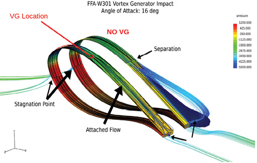 Altair product design example of applying automated meshing to study vortex generation on a wind turbine blade. Image courtesy of Altair.
One way to improve robustness is to simplify the approach, says Corson. His company is researching the use of new solvers, or repurposing existing solver equations. “Another way to go around the bottleneck is to use simple techniques, like Lattice Boltzmann. It is not meshless; it is a simple mesh. It marks the cell as intersected by a surface, then the solver figures out how to deal with it.”
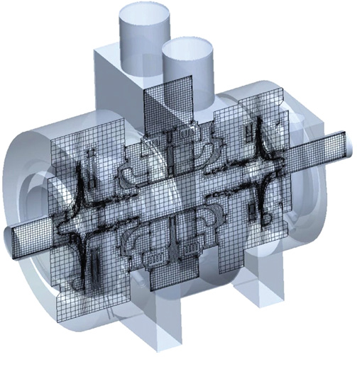 Improvements in Mentor’s simulation software allow custom meshing, as in sectional analysis. Image courtesy of Mentor/Siemens PLM Software.
The third problem NASA cites involves computational performance issues. It isn’t merely a case of faster computers, but of issues surrounding the use of those computers. Some CAE codes are licensed so that each core in a CPU requires a separate license payment. If you run the analysis in an HPC (high-performance computing) cluster or a cloud environment, 1,000 cores will require payment of 1,000 license fees. Some codes won’t run in parallel, negating their ability to work in today’s massive cloud or GPU (graphics processing units) compute environments.
ConvergeCFD is a relatively new CAE company working to achieve the vision of the NASA study with what they call autonomous or run-time meshing, using adaptive mesh refinement. “We don’t want invisible mesh; we want the user to have control,” says Keith Richards, a vice president at ConvergeCFD. Engineers decide the best settings, to strike a balance between mesh size, cell count and level of detail in the results. The mesh is created at runtime, based on the settings.
The goal is to make a solver that can be used early in design by designers, so that basic problems can be solved before the engineering is locked in. Richards describes the process as more about creating company standards, not unlike setting CAD standards. “Somebody already took the time to determine the right settings,” allowing design engineers to run a quick study at any time.
The largest CAE vendor, ANSYS, has not been quiet regarding the future of meshing for simulation and analysis. They recently introduced Discovery Live, a new tool for what they call pervasive simulation. The goal is to create CAE software that makes sense for use by the large percentage of engineers who currently never run analysis software. ANSYS Discovery Live, which is available as a technology preview, taps into users’ NVIDIA GPUs in parallel to allow engineers to pose what-if questions, explore design scenarios and get immediate feedback via instantly updated simulations, according to the company. “The what-if questions are important,” says S. Subbiah, vice president of global product operations at ANSYS.
Simulation tools should also be design tools, says Subbiah. “Accuracy [during design] is the wrong approach. You need directional accuracy.” To achieve the goal of invisible meshing requires improvements all across the board, he says.
All the CAE vendors interviewed for this article agree the issues surrounding meshing are multifaceted. Some are developing new algorithms or new techniques, while others look to increasing computing power. The common goal is to get accurate results fast enough to streamline the engineering process and remove the bottleneck that meshing has become.
Going forward, there are seven avenues of continuous development simulation vendors are exploring. Many will allow more use of simulation upfront in design, others will improve the specialist’s role in finding the perfect solution.

Randall S. Newton is principal analyst at Consilia Vektor, covering engineering technology. He has been part of the computer graphics industry in a variety of roles since 1985.
Follow DEJoin over 90,000 engineering professionals who get fresh engineering news as soon as it is published.


About Us · Contact Us · Editorial Team · Advertising · Privacy Policy · Subscriber Services · © 2026 Digital Engineering 24/7 · Peerless Media