The Rise of Design Software for 3D Printing

Voxel-based 3D printing with NVIDIA GVDB (GPU voxel database), where the inside structure is optimized based on stress and automatically generated. Image courtesy of NVIDIA.


Latest News
April 1, 2018
Ten years ago, design software users lamented that some of their designs might never see the light of day because the complex surfaces, structures and beams they could depict in pixels via their CAD software, could not be machined, molded or manufactured in the real world. Now, the tables have turned. Some delicate features and structures that could be produced with 3D printers may prove impossible to model in a standard CAD software package.
The 3D printing market is at $6.063 billion, according to the analyst firm Wohlers Associates (Wohlers Report 2017). The firm noted: “Ninety-seven manufacturers produced and sold industrial additive manufacturing (AM) systems in 2016. This is up from 62 companies in 2015 and 49 in 2014.” The swelling number of industrial systems suppliers suggest AM has evolved from a prototyping technology into a viable means for mass production.
For the design software industry, the proliferation of AM hardware is a boon and a test. The software developers and suppliers stand to benefit from more people turning to 3D modeling software to create printable designs. But the AM pie may be out of reach for those who are not nimble and adaptable enough to cook up modeling techniques compatible with 3D printing.
Blending Parametric CAD with AM
Parametric CAD was developed as a modeling solution for the subtractive age, for the era of machine tools. Consequently, from the way you create holes to the way you round out sharp corners, parametric CAD mimics the subtractive manufacturing methods. The geometry permissible in the software also reflects the range and limitations of what’s best for mass production in subtractive manufacturing.
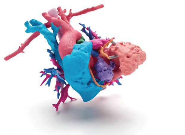 A full-color, 3d-printed model of a human heart used to enhance presurgical planning. Image courtesy of HP; data courtesy of Phoenix Children’s Hospital; Heart of Jemma.
The finite element analysis (FEA), simulation and computer-aided manufacturing (CAM) software programs in the current market also reflect the historical dominance of subtractive manufacturing. The well-known FEA programs employ solvers and setups that let you evaluate the various types of geometry sculpted in subtractive-centric CAD software. CAM software use time-tested machine-tooling principles to identify failures imminent in machining operations.
“There have been attempts by existing CAD vendors to address the need for AM,” observes Arjun Aggarwal, AM startup Desktop Metal’s VP of business development. “Some augment their existing tools with new ones. Others make plugins that can be shoehorned into the current products. Topology optimization software is a good example of that kind. But the problem is, to optimize something, you need design input [in the form of 3D geometry]. Usually, that shape is made with traditional modeling software that reflects traditional methods.”
Using AM-centric simulation and optimization methods on geometry sculpted in subtractive-centric CAD programs is, at best, a compromise. Parametric CAD software developers are gradually adding AM-centric geometry-sculpting features to their flagship products, but it will take some time before CAD programs can fully exploit AM hardware’s capabilities.
“No doubt, existing CAD tools lack some key capabilities to fit design for additive manufacturing,” says Roy Sterenthal, VP of software products at 3D Systems. “However, we do not expect the design world to adopt new CAD and FEA solutions just for additive. Instead, we do see a need for complementary solutions to existing CAD and FEA solutions to fill the gap.”
Hardware Makers’ Software
The software gap is filled, for the time being, by AM hardware makers. At the SOLIDWORKS World 2018 user conference (SWW18), 3D Systems CEO Vyomesh Joshi joined SOLIDWORKS CEO Gian Paolo Bassi in a press conference to announce 3DXpert for SOLIDWORKS, developed to let SOLIDWORKS CAD users prepare and optimize their design for AM projects. “I believe [3DXpert for SW] is the tool to democratize 3D printing,” says Joshi.
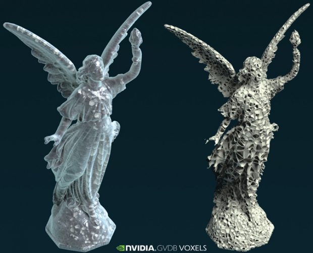 Voxel-based 3D printing with NVIDIA GVDB (GPU voxel database), where the inside structure is optimized based on stress and automatically generated. Image courtesy of NVIDIA.
The original 3DXpert is described as “an all-in-one solution for metal additive manufacturing.” By contrast, 3DXpert for SOLIDWORKS is designed to tackle both metal and plastic design for additive. Whereas the standalone version of 3DXpert operates independently, 3Dxpert for SOLIDWORKS is nested inside the design software, allowing SOLIDWORKS users to design 3D printable parts from the familiar interface.
“Additive manufacturing’s promise is for more shapes, more ways and ultimately to provide design freedom: If you can design it, you’ll be able to print it. However, getting additive manufacturing right is not easy to achieve and new software tools are required to facilitate it. Software solutions are required to provide both analysis tools as well as geometrical tools,” says Sterenthal.
Growing vs. Cutting
Also in attendance at SWW18 was Desktop Metal. Founded in 2015, the company is a relative newcomer to the scene, but its team is a roundup of CAD veterans. The firm brought its production system to SWW18 to join the AM Symposium. The company describes its technology as “a new approach to metal 3D printing—single pass jetting (SPJ). Created by the inventors of the binder jetting and the single pass inkjet processes, SPJ builds metal parts in a matter of minutes instead of hours.”
The company also gave sneak peeks of some code brewing in its lab—including a software program called Live Parts. It’s described as “an experimental technology that applies morphogenetic principles and advanced simulation to auto generate part designs in minutes.”
“Basically, you identify the areas in your parts that you want to connect,” says Andy Roberts, Desktop Metal’s software engineer for Live Parts. “The user can identify forces, but they’re different [from typical FEA loads]. They’re shape-affecting forces that guide how the structure grows. The software grows the part without any preconceived notions of what the result is supposed to look like. The process is much simpler, much more organic.”
In many topology optimization programs, the user provides a generic block of geometry as the starting point. The software uses load calculation, stress analysis and other means to remove as much materials as possible to arrive at the optimal—or the lightest possible—geometry. To start from a blank space and grow materials where needed, as Live Parts does, is the opposite. It’s a radically different approach.
The parts are subjected to not only the forces specified by the engineer, but also to the unanticipated ones, according to Roberts. “Your design is subjected to what we call transitional forces, similar to the random, fluctuating forces you see when the wind is blowing on a tree,” he said. “We found that parts grown this way distribute the stress loads evenly and it reduces hot spots for strains.”
“Live Parts as it is right now is a general shape-finding tool. It doesn’t inherently consider the manufacturing method you would use [for example, injection molding, machining or 3D printing]. But because the parts are geometrically complex, most often, you might find that the part modeled in Live Parts can only be manufactured in 3D printing,” says Aggarwal. “Eventually, as we build more functionalities into it, Live Parts will have direct ties to the Desktop Metal ecosystem.”
HP Enters
SWW18 also marked HP’s introduction of its HP Jet Fusion 300 and 500 series printers. The company writes, “HP Multi Jet Fusion (MJF) Technology has the unique ability to produce parts with controllable physical and functional properties at each point in a part”—something HP describes as “voxel-based printing.” While developing the MJF hardware, HP had also been quietly developing a software program to control print properties of parts at the voxel level.
“There are currently a few experimental software tools in the market, but most professional CAD and simulation software isn’t yet ready to support HP’s voxel-level 3D printing,” explains Luis Baldez, HP’s 3D printing software business leader. “However, HP has started establishing strong partnerships with some of the world’s leading CAD and simulation companies to align our roadmaps and ensure that MJF’s advanced capabilities are fully supported. Siemens, Autodesk, Materialise and SOLIDWORKS are among the leaders who have already taken the first step and are releasing products to specifically support HP’s advanced 3D technology in the marketplace.”
Last year, at the GPU Technology Conference hosted by NVIDIA (GTC 2017), HP Labs and NVIDIA showcased an experimental software program, dubbed GVDB. To break down the name, G stands for the GPU; VDB stands for voxel database. GVDB’s ray-tracing rendering and GPU-driven performance acceleration is GPU maker NVIDIA’s contribution; the software’s voxel-based simulation and optimization come from HP Labs, according to Andrew Page, NVIDIA’s product manager for GVDB.
New Ways to Draw
Whereas complex microstructures like lattices and honeycombs cannot be machined, they can now be produced using 3D printers. Lattice-filled metal parts can weigh significantly less than their solid counterparts, yet carry equal or almost the same strength and durability. Therefore, aerospace and automotive engineers seeking to reduce weight in their products often explore such geometric patterns. Currently, however, they’re not easy to model or simulate in CAD.
“In the past, we were able to design parts we couldn’t produce; now, we have parts that we could make, but cannot design in the CAD system.”
— Andreas Vlahinos, principal, Advanced Engineering Solutions, DE’s online roundtable, January 2016
“Geometric representation is the most important new issue that’s come along with this new wave of generative design tools,” says Bradley Rothenberg, cofounder and CEO of nTopology. “For example, today, the primary way we represent parts output from generative design was once alien to CAD, yet standard in simulation: the mesh. The two major CAD kernels, Parasolid and ACIS, are just now starting to support modeling operations on meshes. Lighter weight representations are also now being used for lattices like beams and shells.”
“Current CAD packages represent lattice and honeycomb structures as meshes, detailing every single element individually. This requires an incredible amount of processing and memory to create, edit and render for the 3D model. And the output file can take hundreds of gigabytes, essentially limiting the designs that the hardware can produce,” notes Baldez.
The de facto standard for 3D printing is currently STL (stereolithography), a format supported by most CAD programs. But moving forward, AM hardware makers and AM-targeted software developers may seek better alternatives to match what the printers can do.
One rival to STL that has emerged is the open, nonproprietary 3MF, championed by the 3MF Consortium comprising Microsoft, HP, PTC, Siemens and other tech leaders. “Our goal is to provide a specification that eliminates the issues with currently available file formats, and allows companies to focus on innovation, rather than on basic interoperability issues,” announces the 3MF Consortium on its homepage.
“3MF recently approved a variation of our [nTopology’s] LTCX beam & shell representation,” says Rothenberg. “Other representations of 3D volumes are also now used in [nTopology’s software] Element. For example, when you want to transition from lattice to solid, we use a function that represents the signed distance to the surface—signed meaning that inside the surface, the distance is negative and outside it’s positive. From this volumetric representation you can then also go directly to simulation or to manufacturing without meshing ... All of these new representations are starting to gain popularity for tasks that would be impossible with classic NURBS b-reps.”
“Traditional CAD packages are based on 3D modeling kernels that only represent the surface of the object, also called Boundary Representation or B-Rep,” explains Baldez. “They assume each part is of a single color, texture and material. The voxel-based parts need to be designed outside the existing CAD packages with lots of workarounds and hacks ... The 3MF team is already working on lattice structures and voxel representations.”
Integrated FEA
Mainstream CAD programs now incorporate basic stress analysis and simulation tools, but for the most part, design and FEA environments are separate, allowing the user to design and analyze sequentially. Software targeting AM tends to use FEA or simulation in the background as part of its form-seeking and shape-optimization algorithm.
This is the case with nTopology, which describes its technology as a “combination of generative, manual and simulation-based design tools ...” nTopology’s product Element is available both as a free version and a fee-based professional version. “With Element, you can optimize lattice structures with respect to user-defined inputs, imported data or our integrated FEA. You input what you know and what you need, and then we generate designs with the user’s guidance,” says Rothenberg.
“Design for additive manufacturing needs to use FEA tools as part of the design process and not only for final simulation and functional approval. This must be done as a continuous process with immediate feedback to the design decisions,” says Sterenthal. He adds, “[In 3DXpert,] extensive analysis tools, including FEA analysis, are incorporated into the design and preparation for additive manufacturing with immediate feedback to apply modifications to the model.”
The Convergence of Design and Manufacturing
In March 2017, startup Frustum announced a partnership with Siemens. The company wrote: “We are excited to enable Siemens NX customers to design fully optimized parts, ready for 3D printing, as well as empower them to move beyond the boundaries of traditional CAD geometry.” Jesse Blankenship, CEO of Frustum, describes the company’s technology as “functional generative design,” pointing out that their proprietary geometry kernel TrueSOLID “allows for blending indeterminate generative geometry to traditional surface based CAD with engineering precision, pushing additive manufacturing to its limits.”
Partnerships between design software and AM hardware makers will increase, as each needs the expertise of the other to enable AM. At the most basic level, design software needs to be printer-aware to help orient the parts in the print tray for optimal part strength and printing efficiency.
Parametric CAD has a significant learning curve, especially for those with limited engineering background. Adding new tabs and commands to accommodate AM design, while necessary, also carries the risk of added complexity—creating a difficult balance for established parametric CAD vendors.
The new breed of standalone AM-specific programs look and operate more like topology optimization programs, less like CAD modelers. Therefore, standalone design-for-AM software may emerge as a separate class of its own, or a subsection of the simulation software market.
The innovation made possible by AM cannot be realized unless it’s supported by the design software. By the same token, existing design software makers realize they must find ways to facilitate AM to remain relevant. Thus with their fates intertwined, the two disciplines are learning to dance to a new beat.
Subscribe to our FREE magazine, FREE email newsletters or both!
Latest News
About the Author
Kenneth Wong is Digital Engineering’s resident blogger and senior editor. Email him at [email protected] or share your thoughts on this article at digitaleng.news/facebook.
Follow DE