
Straddling 2D sketching and 3D modeling, Dassault Systèmes’ CATIA Natural Sketch offers a way to digitally develop concepts in a workflow that mimics pen and paper drawing. Image courtesy of Dassault Systèmes.


Latest News
May 1, 2015
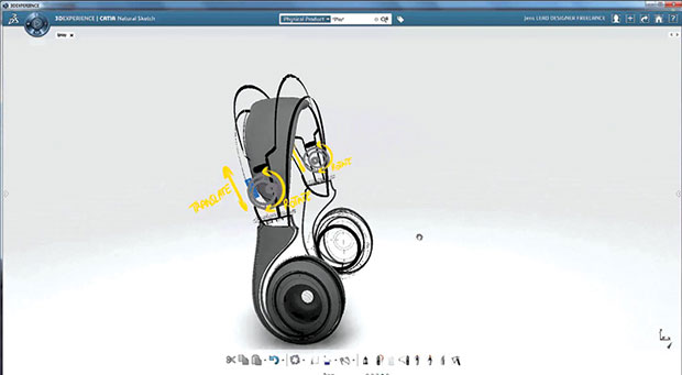 Straddling 2D sketching and 3D modeling, Dassault Systèmes’ CATIA Natural Sketch offers a way to digitally develop concepts in a workflow that mimics pen and paper drawing. Image courtesy of Dassault Systèmes.
The cheapest conceptual design tool is the cocktail napkin on a bar counter. The tiny square invites your spur-of-the-moment bright ideas. Once you have drawn an intelligible schematic or sketch of your concept (not easy to do after the third pint), you can share it, revise it, expand on it and debate it with others. If it doesn’t survive the what-ifs, you tear it to pieces and start again.
Finding the cocktail napkin’s digital equal, however, proves much more challenging. Most mainstream CAD programs are for the detailed design phase, where you meticulously model the outer shape, internal parts and electromechanical components that make up your product. But engineers do not arrive at that stage by the same route.
“People want to do slightly different things in the concept phase, depending on the kind of product they’re trying to conceptualize,” says Dr. Ken Versprille, executive consultant at CIMdata. Their priorities most likely will fall into one of the three classic design objectives: form, fit or function.
“If your major criteria is form [the shape or the look of the product], you would want easy geometry editing. If you want fit [a product that must connect, join, or fit into a predefined space], you may need a parametric modeler. If you want function [the operation of the product], you could explore simulation,” says Versprille. Using these time-tested categories as a guide, looking for the right conceptual design tool is a bit easier.
Digital Napkins
When used on a tablet with a stylus, apps like PTC’s Creo Sketch, Autodesk SketchBook and CorelDRAW closely mimic the 2D pen-on-paper workflow, coming closest to a cocktail napkin. PTC Creo Sketch offers Spline tools in addition to painting tools; the product is meant to augment PTC’s other 3D design apps, like PTC Creo Direct or Creo Parametric.
With digital brushes that reproduce the look of oil, watercolor, pastel and other mediums, Autodesk SketchBook offers a richer environment for artists and can function independently of other 3D design programs. Neither Creo Sketch nor SketchBook gives you the ability to draw with dimensions (the way you would typically do in 2D CAD), but that’s not necessarily a drawback if you’re mainly concerned with rough ideas. You can export the sketches as images into CAD programs for further development. With Creo Sketch, you can export Spline curves for further development in Creo Parametric. With art-centric SketchBook, you cannot export Spline objects; therefore, the use of the sketches created in it may be limited to background layers to guide your 3D modeling.
The CorelDRAW Technical Suite X7 includes CorelDRAW for vector illustration and page layout projects, Corel DESIGNER for technical illustrations, and the Corel Photo-Paint image editor. CorelDRAW and Corel DESIGNER files can be imported into CorelCAD as model space objects with a representation in a layout sheet.
One sketching program that bridges 2D and 3D is CATIA Natural Sketch from Dassault Systèmes. The program lets you use the traditional hand-sketching techniques, but on different working planes in 3D. You may also use the familiar extrusion and projection techniques in the sketching environment. With this approach, you can transform a 2D rough sketch into a 3D model with volume and mass.
Form
When SketchUp debuted as a product of @Last Software in 2000, it aimed to serve a number of industries, including civil engineering, architecture, industrial design and mechanical design. During Google’s ownership (2006-2012), the program grew to become the de facto concept modeler for the architecture industry. With little to no learning curve, the program is ideal for anyone — even those without an engineering or technical background — who wants to sculpt out different concepts as 3D models. Like CAD programs, it offers tools to draw lines and arcs with precision; unlike CAD programs, it doesn’t overwhelm the user with a slew of modeling menus and input fields.
Currently, as a product of GPS and laser device developer Trimble, SketchUp still remains free, and can be adapted for mechanical design concepts, but its tight integration with architecture is evident in the preloaded content (like doors and windows). There is, unfortunately, nothing tailor-made for mechanical or industrial design that rivals SketchUp in ease of use and affordability.
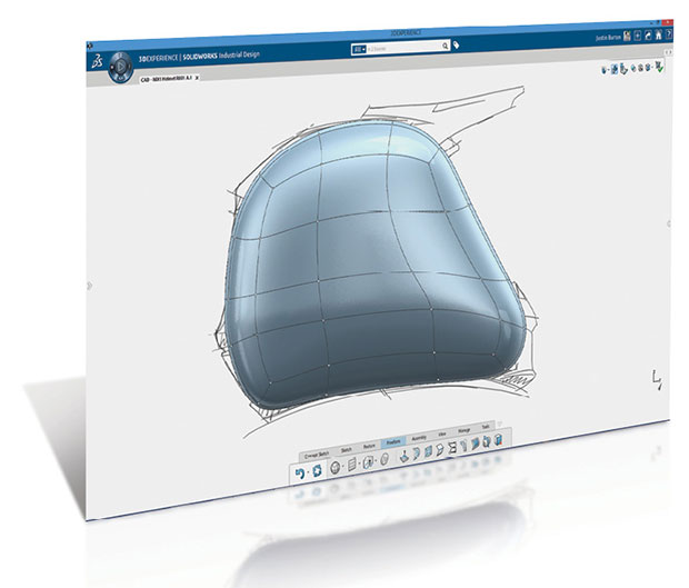 With the introduction of SolidWorks Mechanical Conceptual and Industrial Design (shown here), the company hopes to tackle what it feels is an underserved segment. Image courtesy of SolidWorks.
For creating quick concepts involving classic mechanical shapes, direct-editing programs offer greater flexibility in editing, refining and revising geometry. In programs like PTC Creo Direct, Solid Edge with Synchronous Technology (SE with ST), SpaceClaim, IronCAD and Autodesk Fusion 360, the ability to move, rotate and delete geometric features with no regard for their construction history offers the freedom to explore design options beyond the realm of parametric logic. In some, direct editing and classic feature-based editing coexist. SE with ST, IronCAD, and Fusion 360 fall into this class. Used in conjunction with PTC’s Flexible Modeling Extension (FMX), PTC Creo Parametric could serve the same purpose. Having duality is an advantage when transitioning from the concept phase to detailed design phase.
Anthropomorphic forms and organic shapes are the domain of high-end 3D modeling and animation programs like Autodesk Alias, Maya and Rhino. They’re also the go-to packages for automotive design, where surface quality is of paramount importance. But their learning curve and comprehensive toolsets make them less than ideal for attempting quick form studies.
PTC addresses this segment with its Creo Freestyle module, built on subdivisional modeling techniques. It’s part of Creo Parametric’s modeling environment. The company believes their strategy of a common data model and geometry kernel shared by all of their apps, eliminating any data transfer and/or recreation of models, will significantly improve the handoff between concept and detail design.
With its upcoming product SolidWorks Industrial Designer (previously called Industrial Conceptual), SolidWorks aims to deliver, in its words, “a concept design tool that allows you to quickly generate multiple industrial design concepts in response to a design brief. It offers unique tools for the rapid creation, manipulation, and modification of designs using native and imported geometry.” In pre-release demonstrations at the SolidWorks World user conference, the software exhibits an intuitive NURBS and Spline editing system that allows you to push and pull on control points and vertices to create industrial design shapes.
Fit
Concepts with precise dimensions can easily morph into detailed designs; therefore, some of the classic parametric CAD programs — for both 2D and 3D workflows — may serve the same purpose. For 2D, choices include PTC Creo Layout, AutoCAD, AutoCAD LT, Solid Edge 2D (free), DraftSight (free), DoubleCAD XT (free), CorelDRAW Technical Suite and more. But many of those packages are intended for creating detailed 2D shop drawings with manufacturing dimensions. This means the learning curve and complexity of the software may stand in the way of quick concepts. “Ease of use is a difficult thing to achieve. As you add more capabilities, the program becomes much more complex,” says CIMdata’s Versprille.
PTC Creo Layout, the company explains, is developed specifically for creating 2D concepts that could drive subsequent 3D models. Currently it doesn’t allow you to test load, stress and kinematic motions from the 2D sketches, like some others do.
SolidWorks, an established name in parametric CAD, hopes to address the conceptual phase for mechanical design with its SolidWorks Mechanical Conceptual. As a companion to SolidWorks, Mechanical Conceptual is expected to offer tools for developing concepts with dynamic 2D sketches and morphing them into 3D designs. Even in the 2D stage, the software will allow you to conduct motion and stress analysis. It will also offer direct editing for modifying imported geometry.
Function
Conceptualizing the function of a product (for example, the operations of a heart-rate monitoring wristband) usually falls into the realm of simulation software. But many general-purpose CFD (computational fluid dynamics) and FEA (finite element analysis) programs have the same steep learning curve that prevents detailed CAD programs from becoming effective concept design tools.
Autodesk’s efforts to overcome the hurdle resulted in Autodesk ForceEffect, a Web- and mobile-friendly app that automatically calculates forces and stresses based on simple diagrams. With just a few lines and arcs representing structures (like bike frames, crane arms and bridges), you can verify the feasibility of your design before spending time developing 3D models.
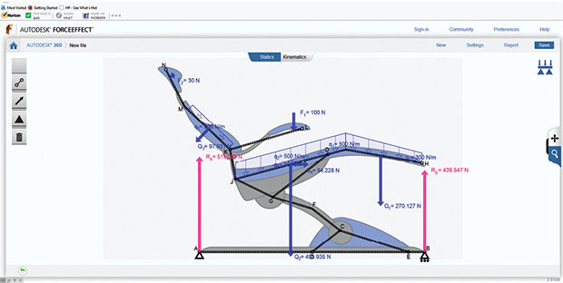 From a Web- and mobile-friendly interface, Autodesk ForceEffect lets you calculate stress, loads and displacements using simple 2D diagrams that represent product structures.
Simulation software developer Altair, known for its HyperWorks suite, believes an easy-to-use duo of shape-creation and shape-optimization software could be the key to encouraging earlier use of simulation. It addresses the need with solidThinking Evolve (NURBS-based modeler) and solidThinking Inspire (for optimization). The latest version of Evolve, released in April, comes with more NURBS-editing tools and a photorealistic rendering option to help you visualize designs. In the Windows-dominated CAD software market, solidThinking’s offerings stand out as one of a handful that support Mac OS, a platform favored by artists and designers.
Some direct editing programs like SE with ST and Autodesk Fusion 360 offer basic simulation tools, enabling engineers to conduct simple stress tests using rough geometric shapes. For those who are willing to employ advanced simulation programs, direct modelers may also serve as a tool to prepare the imported geometry for simulation. Without the shackles of a history-based modeler, a direct modeler allows you to edit CAD geometry with greater freedom. “Some of the direct modelers could be used for functional concept design, because they allow you to simply set things up for analysis,” Versprille says.
Social Collaboration
With the increased popularity of Facebook and Twitter, the use of social media-inspired features — like chat windows, file sharing, discussion threads and group updates — also become part of engineering software, particularly in data management, project management and product lifecycle management (PLM) circles. On their own, these functions do not let you author design concepts; however, they play a crucial role in soliciting early feedback from internal colleagues, external experts, targeted demographics and even the general public.
Such features are the core of products like GrabCAD Workbench, a product spawned from the social legacy of the 3D content community GrabCAD. Traditional CAD vendors are also trying to catch up, by incorporating similar features into data management and design environments. In SolidWorks Mechanical Conceptual and Industrial Designer, the same social media-inspired tools are embedded in the 3D modeling environment. If built on cloud architecture, such tools are well-positioned to capitalize the rising popularity of mobile devices.
“Things are moving more and more toward mobile, toward the cloud,” says Versprille. “Whether it’s insurance or financial software, it has to ride that technology wave. The same with CAD. CAD has to go [to the cloud], because the rest of the world wants to go there.”
The standard feature sets that appear in most mainstream mechanical CAD programs for detailed design are quite similar, an indication that the workflow for this phase is well-established. Not so with the workflow for conceptual design; hence, the elusive nature of a standard toolset for the phase. If someone asks CIMdata’s Versprille to recommend a conceptual design tool, he says, “I’ll have to ask them a bunch of questions to understand what it is they’re trying to conceptualize.” That is perhaps the best approach to tackling the design phase that has no clear definition.
More Info
Subscribe to our FREE magazine, FREE email newsletters or both!
Latest News
About the Author
Kenneth Wong is Digital Engineering’s resident blogger and senior editor. Email him at [email protected] or share your thoughts on this article at digitaleng.news/facebook.
Follow DE

