Helping design and engineering professionals discover, evaluate and specify technologies and processes that shorten the design cycle and enable success.

May 2026 Special Focus: Artificial Intelligence in Design and Simulation
In this Special Focus Issue, learn about the latest developments in the integration of artificial intelligence into engineering workflows.

Design & Simulation Software Guide 2025
In this Special Issue, Digital Engineering presents its second annual guide to design and simulation software vendors.
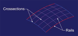 Figure 1: The basic parts to a surface mesh are the rails and cross-sections. The rails go along the sides and the cross-sections join to them. (Cross-sections are generally perpendicular to the rails.) |
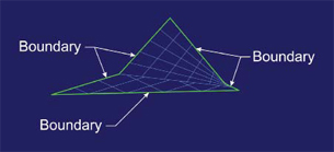 Figure 2: A bounded surface has as many (or as few) edges as are necessary to close the area. These surfaces are very handy for plugging up open holes in your model. |
For the sake of simplicity let’s assume that most of you already know why 3D modeling is so much better than 2D drafting. (Yes, I know what happens when you assume.) You know that with 3D modeling you don’t have to be Leonardo DiVinci and rely on your keen 3D sense to draw those other views of your parts. You know that with 3D modeling you don’t have to draw any views at all. You know that all you have to do is tell the computer where you want the views and it does it for you—perfectly—every time. You know all that right? That’s the assumption we’re going to make. After all, this isn’t an article about 2D versus 3D. It’s about modeling 3D surfaces.
The Basics
What exactly is a surface you ask? It’s very simple actually. In 3D space you need to specify a point to establish location. Usually you do this by referencing a known point called an origin. This origin will represent the zero point or vertex of three perpendicular planes: Zero units in the x direction, 0 units in the y direction, and 0 units in the z direction. Once you find your origin, you can identify your point by giving it a distance from the origin along three axes. Say, for instance 1 unit in the x direction, 1 unit in the y direction, and 0 units in the z direction. This is written 1,1,0. Now you have a point in 3D space. Congratulations!
A point is essentially one dimensional or 1D. Now that you have a location, you need to establish direction. For that, you’re going to need another point. Once you’ve found your second point, you’ve got a line. You now know the beginning of the line, the ending of the line, and every point that exists along the line (between the two points). A line is still one dimensional, but it knows where it’s going. To go to the next level, you’re going to need, you guessed it, another point. Once you have specified a third point you have a plane. You can think of the plane as a sheet pf paper. Everything you do in 2D will happen on that plane. If you drew a line connecting the three points, you’d have a triangle. You would know the end points, every point in between the ends, and (huzzah!) every point that lies in the middle of the resulting closed area. That, my friend, is a surface!
So, when you’re ready to go 3D what are you going to need? Another point. This point is different from all the other points you’ve specified up ‘til now. This point will not sit on your 2D plane. This point will go away from the plane in the z direction. It is this point that establishes 3D. Now, instead of a flat, planar surface you can have anything. You can curve and twist your surface into any shape you want. This transition is momentous. Now you can begin to build 3D objects that can be made in the real world.
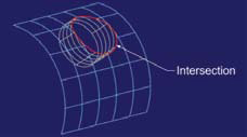 Figure 3: Before surface modelers, intersections were a lot more difficult to visualize. When a cylinder intersects a curved surface, the intersection will not be a circle but something that looks all bent out of shape. |
Different Surface Types
There are different kinds of surfaces you use to build most models. A mesh surface looks like a shape with lines drawn all over it. One set of lines goes one way and the other set goes perpendicular to the first (see Figure 1). The lines are divided into two kinds: rails and cross-sections. The rails generally establish the boundaries of your surface. The cross-sections generally establish everything else about your surface. You need at the very least two rails and two cross-sections for a meshed surface. These are the most widely used surface type.
The next most used surface type is the revolved surface. You take a curve or set of curves and rotate them around an axis. To visualize this, think of the classic example of a flower vase.
The next most common surface is the swept type. Each type of surface gets progressively more complex to create. The mesh just takes two kinds of entities—rails and cross-sections. The revolve needs three—a section curve, an axis of rotation, and an angle to rotate through. The swept surface is the equivalent of an extrude. You take a cross-section curve and move it along a path you define. The nice thing about it is you can define a path in a couple of ways. You can just give it a vector and distance. You can use a rail to sweep along to create what’s called a guide curve. You can even rotate the cross-section as you sweep it. (Picture those ruffled shirt cuffs the pirates all seem to wear in the movies.)
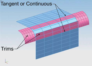 Figure 4: To create a watertight surface model you must make the surface edges meet each other within tolerance, and then trim them. Finally, you need to address the relationships between the surfaces. That means curvature. |
Bounded surfaces (see Figure 2) are the Mr. Fixits of the modeling world. You generally use them when you need to create a surface with a non-uniform perimeter. As long as your boundary curves are contiguous (end to end) they can lay out any shape at all. A really nice trick is to create a boundary surface and then go in with some cross curves and stretch it into a funky shape.
Ruled surfaces use two curves (or sets of curves) set apart from each other. You select one curve, then the other, and the surface will stretch in a straight line between them. It’s quite useful.
Last but not least is the lofted surface. This is a surface that is similar to the swept as well as the ruled surfaces. You create a series of cross-sections—separated some distance from each other—that describe the general shape of your model (imagine your rib cage). The surface will stretch across all of them within the tolerance you set. People use these surfaces to get really complex shapes. It’s like key-frame animation—you tell the surface what to be at each given cross-section.
There are other kinds of surfaces, but the ones just described are the ones you are most likely to use.
In the “good ol’ days” of 2D, if you had a cylinder that intersected a curved surface (see Figure 3), the boundary between the two would be a fairly complicated affair. But that’s not a problem with surfaces. Instead of having to visualize what it looks like—or trigging it out like you might a cam—you just build it and see what naturally occurs. It’s a better way.
Of course that’s not the only thing you can do with surfaces. You aren’t just limited to building your model’s pieces; you can create tools you can use to edit as well. One of the things I used to hate about surfaces was that they were very tedious to build. Just to add a radius blend to the edge of a model you used to have to create the two surfaces that made up the corner, create the radius surface, then trim all of the surfaces to each other to create a “watertight” model (see Figure 4). What a headache!
Nowadays, most surface modeling programs do a lot of the work for you using tools similar to those in a solid modeler. And speaking of solid modelers, the good ones allow you to create and use surfaces. You can use them to achieve shapes not easy or even possible with solid modeling tools. One thing you can do is trim to a surface. You just create a shape, then a surface with a special shape, then use the surface to whack off a chunk of the solid, replacing it with the shape of the surface (see Figure 5). It can work miracles!
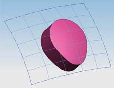 Figure 5: You can use a surface to trim another, or even a solid. This is an easy and fast way to achieve your desired shape. |
Continuity
Of course, no discussion of surfacing can be complete without at least touching on the subject of continuity. Continuity is the relationship between two joined surfaces—how smoothly they transition from one to the other. Continuity comes in two varieties: G and C.
G stands for geometric continuity. C stands for parametric continuity (I know, parametric doesn’t begin with C. Maybe it’s for parametriC?). G describes the shape of the surface and C also generally has G continuity while adding constraints to it. G is the one most commonly seen and is classified as follows: G0 is when things meet at just one point; G1 is when the surfaces meet tangentially; G2 is when they share a common center of curvature. Generally, a G2 continuous surface will be smoother than a G1 surface. When you pay attention to the continuity of your surfaces you get a better, more sculpted surface than you would if you merely blended off the corners. That’s why you see a lot of surface modeling in automotive design.
There you have it, a primer on surfacing. You now know enough to be dangerous to those around you who don’t. You can now use your surfaces to build much nicer models. In fact, with surfaces you can model anything you want. You aren’t limited to what your solid modeler lets you do. And when you’re done, you can shade your model and generate images that look just like real-world objects. (But be careful with that. I’ve had customers that were so impressed with the quality of my images that they assumed they were real and wanted to know how fast we could deliver production quantities.)
| In the world of surface modeling there are the big players and there are the other guys. The big players are: Alias (owned by Autodesk), the de facto standard in industrial design; Rhinoceros (owned by McNeel North America), a very popular and low-cost modeler that also does solids; Think3 (owned by Think3, Inc.), which is industrial design software; ICEM Surf (owned by ICEM Ltd.), which has been used with Pro/ENGINEER, CATIA, and many others; SolidThinking (owned by Altair Engineering, Inc.), which bills itself as an industrial design and styling tool; Siemens’ NX (formerly Unigraphics), a solid modeler that does a remarkably good job of not only surfacing but using surfaces as tools; and (surprise, surprise) SolidWorks (owned by Dassault Systèmes), which not only does some great surfacing but has various third party plug-ins that do what it cannot. |
Surfaces are very useful and versatile tools with which you can do truly wondrous things. Learn to use them and you will advance to a higher level of design and modeling.
More Info
Altair Engineering, Inc.
Troy, MI
Autodesk, Inc.
San Rafael, CA
Dassault Systèmes
Paris, France
ICEM, Ltd
Southampton, UK
McNeel North America
Seattle, WA
PTC
Needham, MA
Siemens PLM Software
Plano, TX
SolidWorks, Inc.
Concord, MA
Think3, Inc.
Milan, Italy
Mike Hudspeth, IDSA, is a senior designer for a global medical company and has been using a wide range of CAD products for more than 20 years. He, his wife, two daughters, and their cats live outside of St. Louis, MO. Send him an e-mail about this article to [email protected].

Mike Hudspeth is a Digital Engineering contributor.
Follow DEJoin over 90,000 engineering professionals who get fresh engineering news as soon as it is published.


About Us · Contact Us · Editorial Team · Advertising · Privacy Policy · Subscriber Services · © 2026 Digital Engineering 24/7 · Peerless Media