The 21st Century Replicator


Latest News
February 1, 2012
by Michael Mock and Joe Titlow
In the science-fiction TV series Star Trek: The Next Generation, a replicator creates food and water during space voyages in the 24th century. Occasionally, replicators even created spare parts, enabling the crew to repair damaged parts onboard the USS Enterprise. This futuristic technology was the concept behind National Geographic Channel’s recent episode of Known Universe. The segment explored a technology, available today, that could allow astronauts to replicate tools damaged or lost in space.
The show’s producers selected 3D scanning and 3D printing technology from Z Corp., which was aquired by 3D Systems last month. Demonstrating how a wrench (or any other tool) could be scanned and then reproduced by a 3D printer, a fully functional, full color “printed” wrench—complete with a moving worm screw—became an Internet and social media phenomenon. The wrench video hit YouTube and went viral, reaching more than 8.7 million viewers.
Clearly, 3D printing captivates the public. To appeal to and explain complex concepts in a 4 -minute video, the producers of the Known Universe series simplified the technology. But there is much more to the story. While it is not possible to simply photocopy an object with moving or hidden parts, we can indeed replicate these objects, with the aid of advanced reverse engineering software.
With that in mind, what follow are explanations of the 3D scanning, 3D reverse engineering software and 3D printing technology behind the wrench video.
Capture with 3D Scanning
The first step in the 3D replication process was to scan the wrench using a 3D scanner. A 3D scanner creates a cloud of x, y and z points in 3D space that represents the visible surfaces of the scanned object. Using a high-definition, portable ZScanner, we produced a full-color, 3D point-cloud model from the physical wrench by passing the scanner around all sides of the object.
The first step in the wrench replication process was to pass a portable, handheld ZScanner 700 CX around all sides of the wrench, to produce a full-color, 3D point-cloud model.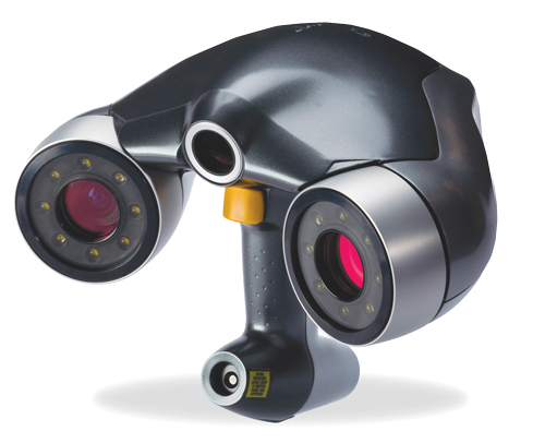
Even though the video did not show a near-exact replica of an object’s scanned surfaces, it is possible to produce one. For example, Z Corp.’s ZScanners have an XY accuracy ranging from up to 40 microns for the high-end scanner, to up to 80 microns for the entry-level scanner. Additionally, the resolution ranges from 0.05mm in XYZ for the high-end scanner to 0.1mm in Z for the entry-level scanner.
The ZScanner couldn’t scan the internal details of the wrench, because it is a laser-based scanner that can only capture surface information within line of sight. We solved that problem with the next step: reverse engineering.
Create with Reverse Engineering Software
One piece missing from the wrench video is the reverse engineering of the 3D scan data into a complete assembly model of the wrench. While the laser scanner effectively captures all surface information that can be seen, the wrench had some internal areas that were not visible to the scanner. We used reverse engineering software to digitally recreate the hidden details, such as the hidden areas of the worm screw. The editors of the Known Universe wrench segment edited this step because of the time limitations of the show segment.
Enter INUS Technology and its Rapidform XOR software. This software helps designers and engineers convert 3D scans into complete parametric CAD models. Using Rapidform, we created a functional CAD model that is ready to print on a 3D printer.
Step 1: Create a 3D Sketch
The first step in almost any CAD model is to define the shape by making a 2D sketch. For this reverse design project, we used a section tool in Rapidform XOR to digitally slice the scan data and generate a 2D sketch outline of the part.
This functionality is much like using tracing paper, and is found in the software’s 2D sketch mode. We wanted to recreate a similar shape using mathematical entities, such as lines and arcs. Using the software, we could easily snap onto the 3D scan data outline while drawing, extracting lines and arcs to map directly to the scan data.
Using 2D sketch tools, the lower jaw was designed to fit the worm screw and the main body.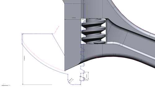
Step 2: Create a Solid
Once the sketch was complete, we followed our normal CAD process again—creating a solid operation from that sketch. We used extrude, revolve, loft and sweep to make solid features. All the while, we were building a history tree with our actions.
We repeated this process several times, adding and cutting away from the model, and literally carving out the correct shape. Our reverse-engineered model contained several advantages over the scanned model:
- It was “intelligent,” meaning it included the design history and constraints.
- Surfaces were geometrically accurate and perfectly smooth.
- It was complete in areas that the scan wasn’t, or couldn’t be (such as the hidden areas we mentioned earlier).
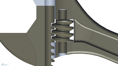
In this cut-away view, you can see the clearance designed into the part to allow a functional part to be printed.
Simply put, the 3D reverse engineering software allowed us to build a copy of the wrench, complete with added colors/features. In the original Known Universe segment, viewers accurately pointed out that the 3D printed wrench was different from the one scanned. The differences between the original wrench and the printed one were done intentionally to demonstrate that once scanned, geometry could be digitally modified before it is printed. Because time didn’t allow this process to be shown in the TV segment, we produced a supplemental video illustrating how a wrench can be scanned and reverse engineered into a complete 3D model that is a printable, functional part (see video, above).
Step 3: Add Mechanical Components
When it came time to add the mechanical components (the worm screw), we again inserted the intelligence needed. To make the wrench work correctly, we needed certain clearances, as well as design intent. The gear teeth on both objects needed to match, or the parts would bind when turned. We added this intelligence and extracted other useful information, such as the pitch of the helix, etc.
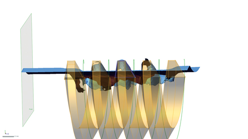
The Helix tool makes it possible to create the spiral thread of the worm screw.
When the reverse engineering of the wrench was complete, we had created a model ready for printing. Our model was also ready for simulation, testing and any other revisions we chose to include.
Print with a 3D Printer
After the reverse engineering process was complete, we imported the 3D CAD file of the wrench into Z Corp.’s ZPrint software. The software sliced the file into thin cross-sectional pieces, and fed that information to the 3D printer.
The printer created the model one layer at a time by spreading a layer of high-performance composite powder build material, and then printing an inkjet binder (with color) in the cross-section of the part. The wrench was built from nothing—one thin layer at a time, with each layer of the powder measuring approximately 0.004 in.
The ZPrinter 450 creates physical 3D models by spreading a layer of high-performance composite build material, then printing an inkjet binder (with color) in the cross-section of the part, a process that repeats itself until the 3D printed model is complete.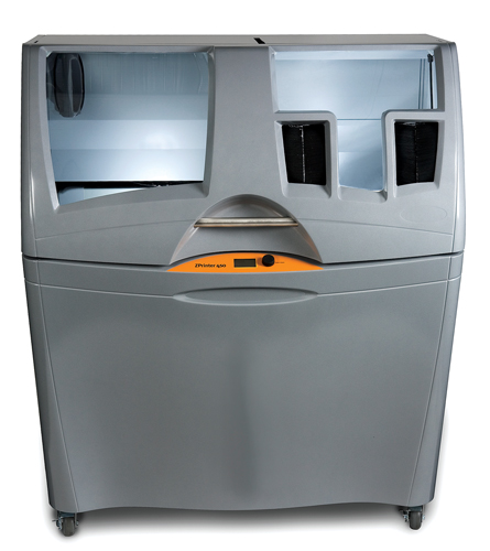
When the binder is printed into the powder, the printer binds the individual powder particles together to create a solid part. The binder not only solidifies each individual layer, it also binds it to the layer below. In less than an hour, the printer “printed” 200 layers, which created the -in.-thick wrench featured in the video.
After the printing process was complete, we removed the wrench and cleaned it to remove any loose powder remaining in the voids around the worm screw. The 3D printer includes an air compressor, which we used to force the powder out of the nooks and crannies. Any loose powder was automatically recycled back into the machine and made ready for the next print.
The Finished Product
As the Known Universe video depicted, we did indeed print a fully functional wrench. This video demonstrates that, with the innovation available today, astronauts on future space missions can use 3D technology to scan, create and print any tool they may need.
Back here on Earth, using 3D scanning, 3D reverse engineering software and 3D printing, we can rapidly design and evaluate not only a wrench, but all types of products. Despite what some of the Known Universe video comments said, these technologies are real and used for a variety of applications, including mechanical design, architecture, entertainment, geospatial and healthcare.
Kudos to the National Geographic Channel for highlighting the incredible potential of 3D technologies. Millions of viewers now know more about innovative 3D tools that are dramatically changing how products are designed, made and tested.
Michael Mock is product manager in the Americas for INUS Technology Inc. Joe Titlow is vice president of product management for Z Corp., which was recently acquired by 3D Systems. Contact them via [email protected].
MORE INFO
Subscribe to our FREE magazine, FREE email newsletters or both!
Latest News


