3D Data at Work
Discover the practical power behind the latest software that makes sense of 3D digitized information.


Latest News
August 1, 2004
By Pamela J. Waterman
Got two or three million data points you’d like to convert into a well-defined 3D object? You’re in luck. Today’s digitized point-manipulation software, operating on typical desktop processors, offers capabilities in detailing and speed hardly seen five years ago.
Whether your end goal is inspection (comparing parts “as designed” to “as manufactured”), polygon mesh modeling (generating files for CNC machines, rapid prototyping or CFD analysis), or freeform surfacing (creating surface models suitable for CAD/CAM system input), you’ll find new software has risen to the challenge of transforming amorphous point clouds into efficient content-rich designs.
 More Points, More Possibilities
Software no longer cares whether the input data is ordered or unordered, and even the end application is not quite such a driving factor: Most packages work for inspection, meshing, and surfacing, but there is still specialization. For example, Verisurf from Verisurf Software (Anaheim, CA) is a low-cost package that compares 3D CAD models with imported inspection points, while MAYA Metrix’s (Montreal, QUE; mayametrix.com) Build!IT software performs real-time and offline inspection, letting users verify the dimensions of highly engineered, critical-profile parts such as aircraft surfaces right on the shop floor.
Build!IT interfaces with all portable CMMs (coordinate measurement machines) and laser trackers, and compares measured data—not only of individual points, but also best-fit lines, planes, circles and spheres—without the delay of offline analysis. It can also create cross sections, curves, and surfaces without needing to transfer to a CAD system, fitting Bezier and NURBS curves to specified tolerances and offsets.
User perceptions are changing, too. Marc Soucy, president of InnovMetric Software (Sainte-Foy, QUE), points out that people are increasingly trusting results from point cloud systems where previously they insisted on CMM-like accuracy.
“There are so many benefits with point clouds,” says Soucy. “Before, with individual points, you just got color maps (showing errors), now you can get gauging and analyze profiles—even the radius of a fillet.” For inspection applications, InnovMetric’s PolyWorks V 8 performs part-to-part comparison and GDandT (geometric dimensioning and tolerancing) analysis as well as best-fit alignments and averaging of multiple prototypes to create a “golden template.”
Most surfacing work starts with generating a polygon mesh that connects the dots, which in itself can satisfy some end needs: RP system input, CNC machines, and even CFD analyses can work off a well-defined mesh. Polymeshing is generally a less-complicated software problem than surfacing, and for manufacturers of many plastic components, toys, or even hidden automotive parts, working from a mesh is good enough (and fast enough) for their purposes. But even these are becoming smoother.
 Left: The InnovMetric image shows how PolyWorks V 8 performs part-to-part comparison using caliper gauges and GDandT analysis on the core of a digitized plastic part. The image is a fusion of the CAD model (gray) and digitized point cloud (yellow) and caliper gauges.

“Inspection is our biggest market share,” says Soucy, “but a newer application in car design is doing digital reviews on polygon models. Some customers are digitizing as many as eight clay models, doing real-time work with PolyWorks in the studio. They save a third of their development time by delivering polygon data to other departments ahead of surfacing.”
Surfacing SubtletiesSince CAD systems generally can’t import large point clouds, surfacing is normally completed in third-party software. How the surfacing is achieved divides the packages a bit, though even those lines are blurring. Jim Clark, sales manager at Metris USA (Rochester Hills, MI), points out that “classical” surfacing (usually counted in days of work) involves fitting multiple individual surface patches to the point cloud; the individual patches are then knitted together to form the complete surface, with great care taken to ensure tangency, curvature, and positional continuity between patches. “Rapid” surfacing, on the other hand, entails creating a high-quality mesh from the point cloud and then automatically fitting a global watertight surface around it. Both methods have their advantages, and indeed some designers use the rapid surface for a first iteration, then refine their design with the classical approach. 
ICEM Ltd. (London, England) recently released ICEM Surf 4.4, an update of one of the most popular packages for Class A surfacing. Its automated processes offer a balance between smoothness and adherence to the actual digitized data, allowing scans to be modeled and diagnosed analogously to working with curves and surfaces; their term is Virtual Clay Modeling.
The two images top left: Steps in using ICEM Surf to import and manipulate data from a digital scan: (Top) Triangulation of a point cloud scan of the front right of a vehicle with feature lines. (Bottom) The same part of the vehicle as a rendered surface model.
ICEM Surf also allows users to define areas of topology (a curve, surface, or just cloud data) and modify them in real time. ICEM Product Marketing Manager Pete Moorhouse explains, for example, “You can take an air vent as a standard off-the-shelf product and feature map it onto another instrument panel, maintaining the tangency conditions to the mating surfaces.”
Imageware V 11.2 is an update of one of the granddaddies of Class A surfacing from UGS Corp. (formerly UGS PLM Solutions; Maryland Heights, MO; ugs. com). The primary module allows direct creation of freeform surfaces from curves, surfaces, or measured point data, supporting both Bezier and NURBS surface patch layout. Another module, Imageware Inspection, performs part-to-CAD comparisons. Imageware V 12, scheduled for a December release, focuses on improved user-interface efficiency, while future enhancements will fully merge Imageware into the UG NX environment, bridging the gap between physical models and production quality surfaces.

At right: The Reverse Engineering Extension provides Pro/Engineer Wildfire users the ability to work with scan data inside their CAD environment. This image is an example of extremely organic geometry of a hip bone from the medical industry, which can be surfaced with relative ease. A solid can then be generated from the surface data and sectioned, cut, analyzed, etc., inside Pro/Engineer Wildfire.
However, in the realm of more “rapid” surfacing, Metris guides users of Paraform via intelligent automation. For example, Paraform’s Feature Extraction automates the process of detecting and creating curves, particularly helping users quickly identify shape transitions.
Feature extraction from point cloud data also figures largely in the latest revision of RapidForm from INUS Technology (San Jose, CA). While its Scan Workbench, Polygon Workbench, Curve Workbench, and Surface Workbench guide users through data clean up, polygon smoothing and decimating, and “shrinking” a NURBS surface on the mesh (including n-sided patches), Feature Workbench lets users extract features or create a base profile for extrusion, and create B-rep solids in Rapid- Form or send the data (sketch curves, surfaces, and primitives) directly into SolidWorks for solid-model building.
Another critical aspect of accurately manipulating digitized data is aligning or registering separate data sets. Richard Barrett, the CopyCAD development manager at Delcam (Windsor, ONT), explains that while they used to align sets to neighbors one at a time, that approach produced stack-up errors. Now, any number of data sets can be simultaneously best-fit together, minimizing errors. CopyCAD offers a Total Modeling approach that lets designers quickly build models by using the most appropriate CAD representation, avoiding, in some cases, the need to complete full surface reconstruction.
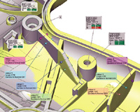
 Right: This is an assembled image of a BMW illustrating the workflow-based approach used by Metris’s Paraform. It can go from point clouds to polygons and surfaces in hours (or days) in an operation that once took days (or even weeks).
Raindrop Geomagic (Research Triangle Park, NC) offers both an inspection package, Qualify, and its automated point-cloud product, Studio. Studio includes a wide collection of tools for scan registration, point preprocessing, polygon creation and repair (including decimation to reduce polygon count), interactive editing (such as removing an embossed part number), feature detection, automatic curvature detection, and automatic surface fitting. The software can also handle models with more than 100 million triangles.
Rhino 3D (Seattle, WA; rhino3D.com) is a low-cost surfacing package that interfaces directly with FARO, MicroScribe, and Romer/CimCore 3D digitizers and can also handle point clouds. It offers inspection, sketching 3D curves, and building 3D models, with all major file formats supported. The Rhino software developers’ kit allows third parties to write plug-ins and add-ons.
Merging into CAD-LandMany traditional CAD products lack the 3D design stream needed to create geometric features and surfaces from digitized data. RevWorks, a SolidWorks Gold Partner application from Revware (Raleigh, NC), incorporates 3D digitizer data from Immersion, Romer CimCore, FARO, and other devices. This package operates as an add-in module with SolidWorks and other devices providing real-time data collection.
Manipulating the TermsAll software packages that combine individual digitized x, y, z locations into meaningful 3D geometry must generally handle the same types of tasks; here are some brief definitions: meshing, triangulating, or polygon generation: The process of “connecting the dots,” creating triangles in between vertices generated by the scanner. polygon editing: This comprises optimizing and manipulating the mesh; optimizing involves smoothing, filling holes, and decimating (reducing the point count), while manipulating changes the mesh by thickening (shelling), mirroring, offsetting, or deforming. curve extraction: Outlining sections of the mesh defined by sets of (traditionally) four connected curves, generally based on NURBS, Bezier, or B-spline mathematics; the process can involve both automatic and manual selections, and the sections may be combined to define surfaces. feature-line extraction: Detecting curves, often automatically, that characterize a region of high curvature change such as an edge or fillet; can simplify representation.
RevWorks provides tools for capturing data, creating best-fit features and surfaces, aligning parts, and managing data collection for parts that are larger than the digitizer’s working volume. RevWorks serves as a PLM tool for capturing as-built data from existing physical parts and design intent from worn or damaged components.
PTC’s (Waltham, MA) Pro/Engineer Wildfire revision offers its own Interactive Surface Design and Reverse Engineering modules, which include elements of wrapping developed with Raindrop Geometric. In addition, it includes its own options for manually or automatically creating surfaces. Designers can combine parametric modeling with freeform surfacing all within the Wildfire environment.
Working from yet a different angle, HighRES Inc. (La Jolla, CA) develops and markets plug-and-play software tool sets that can translate raw digitized data from portable CMMs as native CAD/CAM entities, eliminating data translations issues often found between 3D digitizers and such standard packages as SolidWorks and Pro/Engineer Wildfire.
With all these possibilities, whether you’re salvaging intellectual property on 40-year-old parts, or optimizing the surface of the latest car design, you’re sure to find a suitable tool for manipulating 3D digitized data.
Contributing editor Pamela J. Waterman is an engineer and a freelance technical writer based in Arizona. You can contact her about this article via e-mail c/o Desktop Engineering Feedback.
The Shape of Things to Come:
As Raindrop Geomagic Chairman and CEO Ping Fu says, “Computers handle dots better than lines. If you have enough dots, you can get a high-quality picture or a high-quality 3D shape. Adobe turned fonts into dots—our vision is to take that approach into 3D.” She says that lower hardware and software costs will spread this technology into mainstream manufacturing and beyond, just as desktop publishing migrated from publishing companies to desktop users. —PJW
Companies Mentioned
Subscribe to our FREE magazine, FREE email newsletters or both!
Latest News
About the Author
Pamela Waterman worked as Digital Engineering’s contributing editor for two decades. Contact her via .(JavaScript must be enabled to view this email address).
Follow DE

