

Latest News
November 1, 2005
By Pamela J. Waterman
Software and hardware improvements build off each other to keep this field moving in high gear.
Anyone who believes that one size fits all has never purchased a two-door car, children’s shoes, or finite element analysis (FEA) software. Do you know what FEA capabilities you really need to handle both today’s and tomorrow’s projects? And which software will be a good fit for those needs? Luckily, your options continue to grow. FEA vendors see their business as more dynamic than ever as they anticipate, and respond to, specific user requirements.

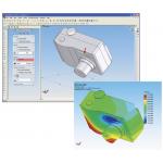
› › Knowledge-enabled and process-centric user environments will enable non-experts to leverage expertise and best practices. CFD specialists will be able to share knowledge, leading to broader use of digital performance simulation in the context of PLM. This image of a constant-suction vacuum cleaner shows flow analysis for predicting efficiency and power, where the power of flow relates to the overall performance of the vacuum. Image courtesy of UGS Corp.
Advances in CPU power, solver design, memory management, and FEA modeling factors have all played critical roles in this process. DE spoke to consultants and vendors across the board to see where the action will be over the next few years.
Vendors of both general-purpose and specialized FEA software agree that users are creating larger models than in years past. One part of this trend is a desire to handle an increased number of degrees of freedom (DOF) in models to more accurately reflect the exact design of a part or assembly.
 |
| A 64-bit version of MSC.Nastran brings together large addressable memory and other improvements for high-performance in handling large models, like this body-in-white model for FEA. |
“I thought there’d be a point where there was enough detail, but it’s not going to stop,” observes Dave Weinberg, president of Noran Engineering. “Models are getting very large because everything is being modeled. For example, in a car interior, designers are including the console, the glove compartment, and even a steering wheel that’s free to rotate.” With such detailed variables and information, even a simple linear static analysis becomes complex.
Chris Reid, ANSYS vice president and GM of the fluids business unit, sees multiphysics driving the growth in model size. “Design and analysis engineers want a systemic view,” he says, “simulating entire systems, as opposed to just components. The model becomes much larger and much more complex, all in pursuit of a much more realistic and accurate portrayal of how a system will behave. Last year we broke through the 100 million DOF barrier for a structural problem, and for fluid problems we’ve been dealing with several-hundred-million-DOF-size problems for some time.”
Making all this possible is a two-pronged evolution in hardware and software over the past few years. Mike Wheeler, who is Reid’s counterpart in the ANSYS mechanical business unit, points out that “computers are getting more capable and the algorithms are getting smarter. This is not just a hardware race; we’ve implemented a host of completely new solver methodologies to address the capabilities that this new hardware presents.” Wheeler adds that the latest configurations of cluster or grid computing, with distributed memory, require a different kind of solver strategy: you must distribute memory as well as CPU power, and do it efficiently.
 |
| This axial inducer model illustrates surface elements for a CFD mesh with 572,000 total nodes—a typical mesh size involved in today’s multiphysics analysis. Image courtesy ANSYS. |
Still, it’s almost a chicken-and-egg situation. Jim Rush, UGS VP of digital simulations solutions, concurs, saying, “Yes, the models are getting more detailed because of the processing environment and the software maturity levels. ]But] the second piece is, we’re seeing larger and larger models being pushed through because people don’t want to simplify away assumptions ]such as surface contact and nonlinear materials] anymore.”
Larger models also result from the increasing numbers of designer-level engineers using FEA tools. Suchit Jain, the vice president of analysis products at Structural Research and Analysis Corp., says that this group of users wants to solve problems as is, whereas (traditional) analysts know how and when to simplify a problem or to use symmetry as appropriate. Jain says the former groups’ approach has now become, “Whatever I see, I want to analyze.”
“Building larger models simply because you can leads to models too cumbersome for innovation,” says Vince Adams, who is the director of analysis services at IMPACT Engineering Solutions and sees this approach all too often. “Much can be learned from simplified representations for sizing and feature placement that solve in seconds.” Adams also cautions that buyers really need to segment themselves into “power” or “moderate” users, and that vendors should acknowledge the differing needs of both.
Capturing the Nuances
Two aspects of this detailing that drive the large-model phenomenon are the desire to include detailed surface-contact conditions such as bolted, pinned, or sliding surfaces, and the need to address fluid-structure interactions (FSI). But why now?
 |
| Image courtesy of SRAC/SolidWorks. |
John Buchowski, who directs product management at PTC, notes that, in the past, including the nonlinear behavior of surface contact meant that solutions lacked accuracy and took unacceptably long times to converge. PTC’s solver technology now takes care of the accuracy issue, and its support of the Microsoft Windows 64 platform reduces the hurdle of solution time. “We see the inclusion of nonlinear contact so prevalent that we include it as a capability even in our base simulation offering.”
Fluid-structure interaction simulations are also in demand. Roxanne Abul-Haj, the principal engineer for ARA Engineering, explains, “Modeling FSI is becoming increasingly important because actual testing for it can take forever. You can save so much time with simulation, but you also have to be sure your programs can handle transients and bidirectional analyses.”
Examples of where FSI modeling is coming on strong include bio-medical and automotive applications. In the first example, blood-flow through arteries is modeled, especially where surgical stents will be used. In the second, automotive companies are closely analyzing how massive airflows impact an expanding (moving boundary) airbag as well as how air, oil, and gasoline flow through an engine block, where high temperatures cause cracking and expansion in the metal. How ‘Bout Them Computers?
There’s no question that hardware advances are leading FEA software developers and users to new heights. Most vendors feel that 64-bit computing and the use of parallel processing (starting with two CPUs) have opened up the next wave of power computing.
“Given the price of advanced FEA and boundary element analysis,” says Bulent Yildir of Integrated Engineering Software (IES), “and the engineering time required to use it, the hardware cost of moving to 64-bit machines is inconsequential.”
Yet mechanical design consultant Tyler Smithson observes that market education is still a ways off convincing users of the need, so mainstream acceptance is not yet here.
64-bit processors can directly access larger amounts of physical memory, as opposed to the typical limitation of 4GB with 32-bit processors; the 64-bit versions can also manipulate data faster by processing more bits per operation. However, as the Intel website states, “64 bits alone does not significantly change the fundamental features or performance of a processor.”
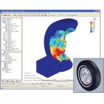
› › ALGOR’s Mechanical Event Simulation software solves for stresses over time, including residual stresses, here in an automotive tire and wheel assembly when the tire impacts a curb. A Mooney-Rivlin hyperelastic material model was used to simulate the large deformation and strain. Click image to enlarge. Image courtesy of Applied Concepts.
Bob Williams, the product manager at ALGOR, notes that you have to constantly keep up with optimizing the software to take advantage of the new structures. “Our entire line now runs 64 bits on Windows, HP-UX, and Linux. We’ve also worked on iterative solvers to let people do things faster on any number of processors: You can run 10 analyses simultaneously, or run one 10 times faster.”
MSC.Software has just announced its own 64-bit version of classic MSC.Nastran FEA software. With a larger addressable memory and other high-performance computing improvements, this package handles the large models demanded by NVH, solid engine models, and fluid-structure interaction.
As part of MSC.Software’s expansion in multidisciplinary analysis solutions, the 64-bit version also offers the ability to perform combined static and transient nonlinear analysis; implicit nonlinear analysis with contact for highly nonlinear deformation problems; explicit nonlinear (LS-Dyna) analysis for problems involving crush, crash, drop tests, and high-impact dynamics; and dynamic motion analysis through the integration of MSC.ADAMS solver.
›› As the robustness and sophistication of meshing applications improves, users will increasingly leverage ‘black-box meshing,” thereby eliminating significant process effort associated with large-scale meshing of complex geometry. NX 4 meshing image courtesy of UGS Corp. Click image to enlarge.
Acknowledging the fact that solvers were not originally designed to run on parallel processing servers, Abaqus developers have also been rewriting their FEA code to take advantage of parallel- and 64-bit processing benefits. Sanjeev Kulkarni, the president of KB Engineering, which specializes in complex nonlinear analysis, finds that Abaqus has put a lot of effort into this task, particularly by creating a good interface between fluid and structural codes.
Regarding parallel processing, IES’ Yildir adds, “Initially this will ]involve] from two to eight processors. The major shift in computing will occur when massive parallel machines become available to the average design engineer; machines with 256 processors or greater will radically change the types of analysis attempted.”
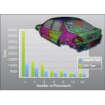
Livermore Software Technology Corp. (LSTC) has already optimized its LS-DYNA transient dynamic FEA software for distributed-memory Unix, Linux, and Windows-based platforms. Wayne Mindle, a senior engineer at LSTC, explains that by switching a 500,000-element crash simulation (with a 120 ms run) from a shared-memory system to a 16-processor parallel system, the run-time dropped from 160 CPU-hours to just 12 hours total.
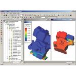 |
| Thermal and stress simulation of an engine sub-assembly in 3G.author. Image courtesy Plassotech Inc. |
ARA Engineering’s Abul-Haj points out that as an additional benefit, having analysis software running on distributed processors (e.g., four workstations) allows a small company to have the same effective computing resources as a large company that operates a single high-performance computer. Stay Tuned For More
Tomi Mossessian, President of Plassotech, certainly believes, in this changing environment, “Not all FEA tools are created equal.” He suggests you investigate examples for quality, efficiency, and robustness under multiple conditions; and look for solid integration with MCAD to achieve what-if studies and full parametric simulation. The latter topics will be included in Part 2 of this trends article.
In the meantime, it might be best to look in a mirror to see just what kind of user you are and where you’re headed, then find a vendor whose products reflect back your same view of FEA life.
Contributing Editor Pamela J. Waterman is an electrical engineer and freelance technical writer based in Arizona. You can contact her about this article through e-mail by clicking here.
Product Information
ABAQUS, Inc.
Providence, RI
ALGOR, Inc.
Pittsburgh, PA
ANSYS, Inc.
Canonsburg, PA
ARA Engineering, Inc.
Mesa, AZ
COMSOL, Inc.
Burlington, MA
IMPACT Engineering Solutions, Inc.
Brookfield, WI
Integrated Engineering Software
Winnipeg, MAN
KB Engineering, Inc.
Tempe, AZ
Livermore Software Technology Corp.
Livermore, CA
MSC.Software Corp.
Santa Ana, CA
Noran Engineering, Inc.
Westminster, CA
PlassoTech, Inc.
Calabasas, CA
PTC
Needham, MA
Smithson Engineering
Crestline, CA
Structural Research and Analysis Corp.
Santa Monica, CA
UGS Corp
Plano, TX
Subscribe to our FREE magazine, FREE email newsletters or both!
Latest News
About the Author
Pamela Waterman worked as Digital Engineering’s contributing editor for two decades. Contact her via .(JavaScript must be enabled to view this email address).
Follow DE

