Helping design and engineering professionals discover, evaluate and specify technologies and processes that shorten the design cycle and enable success.

May 2026 Special Focus: Artificial Intelligence in Design and Simulation
In this Special Focus Issue, learn about the latest developments in the integration of artificial intelligence into engineering workflows.

April 2026 Special Focus Issue: Generative Design
In this Special Focus Issue, Digital Engineering takes a look at how generative design solutions can be used across different types of design problems and with a variety of manufacturing approaches to accelerate design space exploration, and…
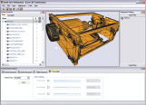
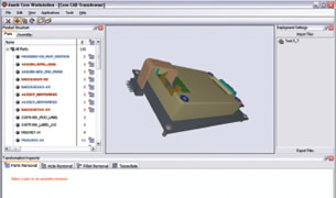 Here, the Remove Parts Delete action is applied to remove specific components. The parts disappear in the geometry window, while the parts or subassemblies are struck out in the structure browser panel to the left-hand side of the user interface. |
Anark is a specialist in animation and visual communication and has been serving many high-tech manufacturing companies (Boeing, Lockheed Martin, Panasonic, and Maserati) for many years. Product visualization and configuration, virtual catalogues, tech publications, interactive training and simulation, as well as sales and marketing presentations are where its history and expertise lie. But recently, the Denver-based company took its wealth of knowledge and created Anark Core, an application set intent on helping repurpose rich 3D MCAD data for a number of different tasks.
There are two products currently on offer: Core Workstation and Core Server. Within Core Workstation, you perform the import of your data and apply actions to remove small or specific parts and features (such as fillets, holes, etc.), define any tessellation controls, and output the data to your formats of choice. This process is then captured as a “recipe” that can be deployed and automated across the enterprise using Core Server. So let’s crack on.
Core Workstation
Core Workstation is where the meat of the work is done; essentially loading and transforming the 3D data. Core includes a number of translation options (including IGES, VDA, and STEP) via proprietary files such as ACIS and Parasolid and then native data from CATIA V5, Pro/ENGINEER, and NX. The UI presents your data onscreen and you have the usual interaction via pan, zoom, and rotate controls. A split panel on the left shows a flat parts list or a hierarchical assembly structure (as this can be extracted from the 3D file) so you have access to assemblies and sub-assemblies as you would natively. It does support reading data from different sources and will try to maintain coordinate positions where possible, but doesn’t have placement tools to position geometry accurately.
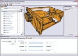
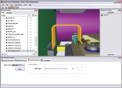 The Fillet removal action allows you to remove rounds and fillets from objects, based on their size, for those looking to automate data abstraction. | 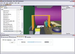 The two images show how the settings affect specific geometry. Here, a rounded sheet metal component has its bends removed (right). |
The Part List panel shows a flattened list of parts (with the hierarchy stripped out). Alongside these, the system shows you entity counts for the geometry types you can interact with, such as the number of fillets or holes within each part. You can also automatically zoom to a part by selecting it and hitting the icon to Zoom In. The next step is to start to apply actions to your parts and subassemblies. The first is to remove parts of a certain size, the thought being that if you’re carrying out visualization or documentation work, perhaps communicating data with a supplier, you want to strip out any small parts that are inconsequential.
The system allows you to vary a slider or dial in a specific value (little tip: the value you enter appears unitless, but is actually the metrically-read diagonal bounding box measure around your current selection). The next step is to remove holes and fillets. Again, this can be done by selecting parts or subassemblies and using the slider or entering in a specific value. The system had a few problems with very complex holes, but for the majority of my cases, it worked very well.
The final step is to apply and control tessellation. If you’re trying to maintain accurate CAD surface geometry, this won’t really be used, but if you’re looking to repurpose data for visual presentation, rendering, or simulation, or to protect the surface-geometry form, then you can adjust the tessellation process with controls for chord height, facet angle, and facet size.
Things to Consider
One issue is feedback. Core Workstation doesn’t include much feedback. Yes, if a part is removed, it’s struck out in the structure panel, and you can see the number of holes and fillets decrease as you apply actions, but you can’t see what you’re actually removing. It’s a bit of an oversight when you’re dealing with complex parts and assemblies as it’s rather easy to lose track of these.
Also worthy of note is the selection capability. If you select the highest level in the product structure and apply an action, it will propagate to every part in the product structure. If you then select a subassembly, you can override the settings for the components within that subassembly branch. Then the final move is singular part override. If there are specific parts that you need to protect, then you can apply an action to them individually. There is also a Protect action, which can be applied to any geometry to override any other action applied to that part as well as the system when exporting the data again. It will preserve it exactly as it was initially.
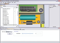 | 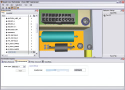 |
| The Hole Removal Action can be seen in action here removing holes from the PCB component toward the bottom of the screen — the image to the right shows that the holes to a specific geometry limit have been removed. | |
Once you have your transformation actions in place, you then choose the output format: CATIA V5 or V4, STEP, VDA, IGES, Parasolid, and Collada (a standard format commonly used in the CG industry). The export process is also captured as part of the workflow, so that can be automated. Once finished, you have a recipe available to read in data, transform it (to remove detail, parts, tessellate), and then to export it. The next question — what can you do with it? If you’re doing this kind of work on a regular basis, then you’re going to want to automate it and this is where Core Server steps in.
Anark Core Server
To take things further and to deliver the Core MCAD data transformation technology across an organization (rather than to individual seats), you need to adopt the Core Server solution. Now, this can work in several ways. It can be run in a Pull environment, where the Core Scheduler application is used to define specific times for recipes to be run on specific data. Or, it can be run in a Push mode, with the PDM server (using a Software as a Service link) directly controlling Core Server, moving specific data through recipes created with Core Workstation, to deliver it on demand or as required.
I understand what Anark is trying to do with the Core products. Within its area of competence (creating lightweight visualization assets from heavy accurate MCAD data), a tool such as Core is invaluable — and if you’re in an industry that requires visualization, it can provide huge benefits. Elsewhere, within the design, engineering, and manufacturing sector, Anark Core can be used in a number of cases.
 |
 Tessellation controls afford you a per-part tessellation control over your exported geometry — this means that critical components can be exported at high resolution (fine mesh), while others can be dialed down and exported with much coarser tessellation settings. |
In the realm of intellectual property protection, your MCAD data represents the physical manifestation of the thought, knowledge, and innovation that goes into a product. Enabling you to remove unneeded detail from a part or assembly and to obfuscate details with tessellation is a powerful protection tool within Core. What’s missing are details for removing internal parts or creating space envelopes within which a supplier can work.
Technical illustration and simulation are growing areas of interest across industry. There’s a drive toward integrating design with technical documentation, but Anark Core’s capabilities to do that successfully requires a greater level of control than is currently available. According to the company, however, this is an area under development and the team is looking to add more granular control in the next release or two.
This leaves us with rendering and visualization. When you’re looking at the creation of live datasets for use in interactive product catalogues, assembly, service instruction assets, and even design review of large-scale datasets, the ability to remove levels of detail while retaining full geometry clarity and fidelity where needed is essential — this is Anark’s sweet spot, both in terms of product and knowledge.
Anark’s products are born from experience working with heavyweight clients and their heavyweight data and, for a first release, the Core offering is impressive. The user experience is simple and self explanatory. Some of the finer points are missing; the features that would make this system shine. But once they arrive, bringing greater control and more feedback combined with the highly automated, recipe-based nature of the suite, Anark Core should assist in solving some serious bottlenecks in any organization. And that surely makes it worthy of further investigation.
More Information
Anark Corporation
Denver, CO
anark.com
Al Dean is technology editor at MCAD Magazine, a UK product development and manufacturing technology journal (mcadonline.com) and is editor of Prototype magazine (prototypemagazine.com). You can send comments about this article to [email protected].

DE's editors contribute news and new product announcements to Digital Engineering. Press releases may be sent to them via [email protected].
Follow DEJoin over 90,000 engineering professionals who get fresh engineering news as soon as it is published.


About Us · Contact Us · Editorial Team · Advertising · Privacy Policy · Subscriber Services · © 2026 Digital Engineering 24/7 · Peerless Media