CAD in CAM: Is It Worth It?
The integration of CAD and CAM in unified (and separate) programs reveals strengthsand weaknesses in the most popular applications.
Latest News
October 1, 2004
By Joe Greco
When people think about CAD/CAM, many really take that slash between the twoliterally, and as a result most use different applications for each. While thisgives the user the best of both the design and manufacturing worlds, it opensup potential interoperability problems. However, many of today’s most popularCAM applications also come equipped with CAD capabilities, so here we look atsome of these programs to see how they compare with today’s MCAD products.
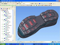
PowerSHAPE ProDelcam’s PowerSHAPE Pro is a separate but tightly interoperable program for usewith PowerMILL, the company’s 5-axis machining program. Upon opening the softwareusers are greeted with a simple and customizable user interface. The main drawingand modeling tools are located at the top of the screen, while the standard views(top, iso, etc.), rendering styles (wireframe, shaded, etc.), and navigation toolsare located on the right. But all that can be changed as seen in Figure 1. Rotating,zooming in on, and panning across 3D models via mouse shortcuts is easy, and weliked the way you can display multiple views and draw between them on differentworkplanes.

Figure 1: Delcam’s PowerSHAPE Pro features a very customizable user interfaceand modeling tools that are relatively easy to use.
Essentially, there are two main drawing icons and three main icons for modeling.Clicking on any one puts you in that mode, thus changing the final icon on thetoolbar so that it displays, via drop-down icons, all the commands related tothat mode.
PowerSHAPE offers three ways to create 2D splines, as well as several other techniquesfor creating 3D curves. (Two examples are automatically locating 3D curves atthe intersection of existing 3D geometry and projecting curves to faces.) Whensurfacing, PowerSHAPE has the usual capabilities like extruding, revolving, andothers, as well as the ability to create a surface from a network of curves andsome powerful surface filleting and blending commands. But the truth is, fiveyears ago these tools would have put the program’s surfacing ahead of what MCADproducts like SolidWorks and Solid Edge were offering at the time. Not today.
Many of PowerSHAPE’s surfacing tools have solid companions. For example, thereis a solid extrude and revolve, as well as solid primitives that complement theirsurfacing counterparts, such as spheres, cones, and cylinders. Fast and easy Booleanoperations are available for the solids, and users will also like the dynamicsectioning capabilities.
PowerSHAPE has all the typical features we expected in a solid modeler—fillets,chamfers, holes, ribs, and shelling, etc.—and can all be edited via a featuretree that works similarly to those found in MCAD applications. It also containssome commands not usually found in a typical MCAD application. For example, thereis an automated tool for creating an electrode, and a tool and die wizard. Thereis also an Emboss command and a powerful Morph tool for deforming solids in acontrolled manner.
Just as important is that most of PowerSHAPE’s commands are easy to use: Wheresome programs have certain rules for how the section and rail (guide) curves ofa sweep must be touching each other, PowerSHAPE includes no such limitations.
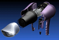
The biggest weaknesses MCAD aficionados will find is that PowerSHAPE doesn’thave a parametric sketcher and is missing some advanced assembly tools, albeitits Explode capability is handy (see Figure 2, below). In short, its modeler willget the job done for some 3D users and it also works well with two fairly uniqueDelcam products: ArtCAM, for turning 2D artwork into 3D models, and Copy CAD,for reverse engineering. An evaluation copy of the software is available at delcam.com.

Figure 2: Delcam’s PowerSHAPE Pro has the ability to explode an assembly.
GibbsCAM 2004
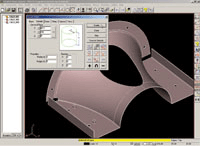
After an install that was trickier than it needed to be, opening GibbsCAM—fromGibbs and Associates—revealed a simple user interface with a standard set of Windowsmenus followed by a series of CAD/CAM-specific menus. There are just a few toolson top for operations such as toggling display mode (wireframe/shaded), displayingthe coordinate system, and more. The main toolbox holds all commands from 2D tosolid modeling to CAM, and it sits to the right of the screen (see Figure 3, right).

Figure 3: GibbsCAM integrates the CAD tools on the same toolbar as the CAM commands.Onthe left are some of the typical solid modeling toolbars the program uses.
To start modeling, you select the Solid Modeling icon, which opens a toolbarcontaining nine tools. The first one creates solids. Clicking on it opens anothertoolbar with seven tools related to solids creation. All these toolboxes are non-modal,meaning they stay open until you close them. (It makes accessing them easy, thoughit clutters the screen a bit.) Two of these seven solid modeling tools are primitives(spheres and cubes); four require 2D geometry for extruding, revolving, lofting,and sweeping; and the final tool allows you to solidify an open shape.
The four tools that rely on 2D geometry are basic and give almost no indicationas to how they should be used. For example, the Revolve command permits the shapebeing created to be turned only around the horizontal or vertical axis; it’s notpossible to pick a line or edge. And while it’s somewhat obvious for veteran CADusers, there are no help prompts or information in the dialog box to help onefigure out what to do. (Technically, there are prompts because there is a wayto activate them, but they only show up for certain tools.)
There are also “advanced” solid modeling tools for creating fillets and chamfers,adding draft, shelling, and more. These commands are all basic and again not tooeasy to use due to poor feedback. As an example, the Shell command only seemscapable of creating hollow parts; we couldn’t figure out how to remove a face.And when trying to create a fillet, there was barely any visual screen feedbackto indicate that we had actually successfully selected the desired edge.
The main Solid Modeling toolbar also contains Boolean operations that work prettywell and some surfacing commands. The surface revolves, sweeps, and so on havethe same limitations as the solid commands, meaning they are pretty basic. Thereis an Extend surface command, which would have been more helpful if it didn’talso automatically untrim the surface; this should be an option. In addition,we couldn’t get the Coons patch to patch any geometry we imported.
Creating 2D elements in GibbsCAM uses an antiquated technique that we haven’tseen in a while. Whatever you want to create—be it circles or splines—points mustbe placed first. If you can stand doing this, the program does actually have somepowerful 2D tools. For example, there are two ways to draw a spline: Control pointsand Fit (through points). The latter has four options, several of which are specificfor more control of the toolpath that will eventually be generated. While thereare tools to create the base geometry, GibbsCAM does not have a parametric sketcher.
By double-clicking on a shape, the program hides it by putting it into an areacalled the Body Bag, which has to be one of the creepiest names ever used in thehistory of the CAD/CAM industry.

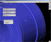
Figure 4: PentaCut from CAMtek is shown here creating a solid primitive. Thesoftware also features a browser tree and some unique navigation capabilities.
PentaCutCamtek develops PentaCut as well as several other products with the same CADengine. Just as we went to press, we got a quick look at the former. It seemsto have some fairly powerful 2D drawing commands, including the ability to createsplines, slots, hyperbolas, and parabolas. There are also 3D modeling commandsthat let users create primitives as well as extrude, sweep, and revolve 2D geometry.The primitives work well and basic features can be added to them such as fillets,chamfers, and shells. The program also has Boolean operations. 2D geometry thatis extruded, swept, and so on, creates surfaces that can be thickened into a solid.
PentaCut could benefit from a user interface overhaul. Some commands are a littletricky. For example, to select 2D geometry for a 3D command like Extrude, it hasto first be converted into a “figure,” something that not only adds extra steps,but the process is not obvious. Most other commands are not too difficult to use,but the overall look and feel is antiquated, and common Windows features, suchas an Edit Menu, are missing.
Don’t Quit Your Day CADSo while the idea of true integrated CAD/CAM is an appealing one, most userscreating serious components may struggle when using the applications we lookedat here, albeit PowerSHAPE does hold some promise. If you’re looking at an investmentinto 3D CAD/CAM, our advice is to pick the best separate design and manufacturingapplications that you can afford and then determine if any possible interoperabilityheadaches will prevent the two from working together in a reasonable fashion.If you absolutely need an integrated CAD/CAM, your best bet might be an applicationwe didn’t mention here—but have reviewed many times before—VX CAD/CAM from VXCorporation (vx.com).
Joe Greco is a Desktop Engineering contributing editor. You can send Joe yourthoughts on this article via e-mail c/o Desktop Engineering Feedback.
PowerSHAPE Pro
Delcam
delcam.com
GibbsCAM 2004
Gibbs and Associates
gibbscam.com
PentaCut
Camtek Limited
peps.com
VX CAD/CAM
VX Corporation
vx.com
Subscribe to our FREE magazine, FREE email newsletters or both!
Latest News
About the Author
DE’s editors contribute news and new product announcements to Digital Engineering.
Press releases may be sent to them via [email protected].


