Latest News
February 1, 2008
By Abdul H. Shammaa
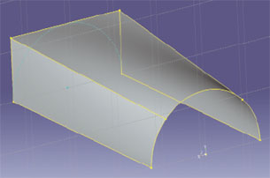 Figure 1: A loft defined by its start 2D sketch (half circle) and its end 2D sketch (open box). |
Every engineer would love to fire up his favorite application, import a file from his co-worker or client, and get to work. Rarely does this happen smoothly for models with any complexity. There’s almost always something wrong with the exchanged data, and engineers can spend hours or days repairing the file or rebuilding it from scratch.
And there’s a good reason that this is so, and will remain so.
Every MCAD platform reflects a constantly evolving theoretical foundation and product improvement roadmap that its developer believes holds the greatest benefits for its users and business strategy. Radiating off this foundation is a mind-boggling array of formulae and algorithms to execute the commands that you use. The user interface is a shell that invokes these calculations and lets you be an engineer and not an expert programmer versed in the latest algorithmic generation and surface manipulation theories.
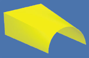 Figure 2: This image is the same as Figure 1 only as seen by the data translator,CADdoctor. |
Even the simplest MCAD file is a complex mathematical representation of a developer’s set of algorithms that define an image’s taxonomy, topology, entity relationships, and so on down the line across such routine items as edges, fillets, surfaces, and layer-storage procedures. Each developer handles these however they think best. For example, different applications might represent a curve as a b-spline, as a list of curve segments, or as a NURB. Each would do the job. But it’s like Chevy and BMW. Both cars have parts that render the same service. You just can’t use Chevy parts in a BMW.
Wide variability in data types and methods holds true even if two applications use the same foundation kernel. Kernels are like root languages: they offer broad latitude in implementation and interpretation of their rules. This makes the kernel subject to corporate programming philosophies, business strategies, and even such banal human factors as, “I think this command should work like this.”
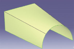 Figure 3: This view shows the loft from Figure 2 as seen in the target MCAD Note that Figures 2 and 3 look identical, having the same number of surfaces,edges, and points. |
Kernels also have capabilities that, similar to slang’s effect on spoken language translations, defy direct translation. For example, ACIS supports both manifold and non-manifold geometry, which enables it to connect a surface and solid at an edge in the same part. ACIS allows a part to have three surfaces connected to an edge, whereas most solids allow only two connections at an edge. So, attempts to translate a tri-surfaced part for a non-ACIS kernel are doomed to failure because there is no direct algorithmic parallel.
The Tricky Part
Since MCAD files are the media that convey the content that affects and shapes the operation of CAE, CAM, PLM, and other engineering and manufacturing applications, it would seem natural that MCAD vendors would develop comprehensive data-translation solutions. It’s likely not going to happen. Data translation is a separate discipline. It makes business sense for MCAD vendors to stay focused on design software while leaving data translation for third-party specialists because translation is a complex specialty.
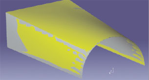 Figure 4: The CADdoctor screen shot shows a single-window overlay of the source file (Figure 2) andthe target file (Figure 3). The points of difference between the two are readily apparent. |
Dedicated data translation solutions mathematically deconstruct a native file, then reconcile the translation to the mathematical expectations of receiving target platform, be it CAE, CAM, MCAD. That’s a tricky business, and the more content you wish translated, the more complicated the job becomes.
Even seemingly simple data translations are complex. For example, take the problems presented by translating a circle from an MCAD system using periodic geometry and one that uses non-periodic geometry. With periodic geometry if you go from 0 to 2pi or 0 to 4pi on a circle, you return to the same location. You can query that circle at any angle value and get a number (x) back.
In an MCAD system that handles circles as non-periodic geometry, you can only query a location along a circle between 0 and 2pi. Anything above 2pi does not compute.
When you translate a circle with periodic geometry (4pi) to a target platform that uses non-periodic geometry, it probably would not accept the 4pi as is. A dedicated data translator can translate the periodic geometry-based circle by dividing it by origin and radius and a top location and sweep angle. Or it can define the circle as a NURBs curve.
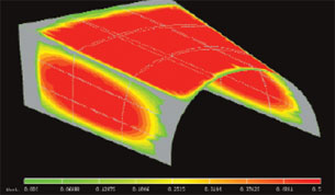 Figure 5: This image from CADdoctor’s Geometry Verification tool shows the contour of difference between the source file and the target file. The units on the color scale are millimeters. The differences between the files resulted from the different mechanisms used by each MCAD platform to generatethe loft’s geometry. Both files, however, satisfy the original loft definitions in Figure 1. |
Both approaches give you equivalent geometry, but they are not equivalent mathematically. They are very close — 10-14 close — but they are not clones. This is because NURBs do not store the origin or radius of a circle, they use control points to define the circle. The data translator has to back-calculate the origin and radius from the geometry of that NURB. Whenever you back-calculate, you get noise.
Here’s the trickiest part: the result of a data translation may look the same to the naked eye. For example, Figure 1 shows a loft in Elysium’s CADdoctor data translator. You can see that the loft is defined by a start 2D sketch (half circle), the end 2D sketch (open box), and four rails.
Figure 2 (above) shows the same loft in the originating MCAD file. The view in Figure 3 (right) shows the loft as imported into the target MCAD platform. Figures 2 and 3 appear identical.
Now look at Figure 4. Here, CADdoctor’s data translation validation tool overlays the source code from Figure 2 upon the imported file (Figure 3) in a single window. It’s readily apparent that the two geometries are different. The contour map in Figure 5 shows you just how dramatic the difference is between the source and translated file.
Is this a bad translation? Yes and no. The same loft definition (i.e., 2D sketches and guide rails) produces geometrically different lofted surfaces because each MCAD system has its own algorithm to generate lofted surfaces. Both files are correct, since each satisfies the constraints of the 2D sketches and the rails on the generated surfaces. This translation would be bad only if you expected — and needed — to receive a clone of the original.
What About STEP?
The most widely used alternative to dedicated data translators is STEP, a version of which comes with every MCAD system like a home computer comes with a notepad word processor. STEP is data translation by international committee. The object of the STEP standard is to create a universal, computer-independent file format for a broad range of industries such as manufacturing design, machining, and shipbuilding.
STEP translates a model by defining it as a group of standardized shapes known as neutral entities. Neutral entities are a shape’s lowest common denominators, which is probably why a STEP translation is called a “dumb solid.” Depending upon your needs, it’s not always bad getting a dumb solid. For example, if you want to outsource a model to a third-party machine shop, you would want them to have just enough information to machine a part. You do not want to hand out intellectual property.
The problem with STEP is that your MCAD exports a generic STEP file based on its implementation of the standard and your target system imports the file using its own STEP implementation. STEP is extremely large — tens of thousands of defined shapes. Consequently, developers avoid the excess overhead or eschew modifying their code to appease a standard by supporting some of it, a lot of it, or most of it. Some MCAD systems offer users a handful of STEP default settings; however, it is not axiomatic that users know the difference between AP204, AP209, AP203ed, and AP214.
Be that as it may, the STEP implementation in the originating and target systems might not be in synch or support the same entities. This is why you can get STEP translations that are not just dumb solids — they are occasionally useless. In comparison, a dedicated data translator renders a STEP file that takes into account the target system’s expectations.
Furthermore, STEP does not have a suite of tools to verify the accuracy of a translation (they’re still under discussion). This leaves it up to you to determine what went awry with your data translation.
Stepping Beyond STEP
Data transformation is the difference between a dedicated data translation solution and a universal neutral data exchange format, be it STEP, IGES, Parasolid, or STL. A neutral data exchange format gets something exchanged, leaving you to figure what and how to fix problems. But the neutral format by its nature does not address the unique characteristics of the hand-off from the data source to the target software.
Elysium acquired its translation expertise by collaborating with individual developers to engineer a data translation solution that thoroughly understands the mathematical functioning of their software. MCAD, CAE, CAM, PLM developers may not publish their entire suite of APIs (applications programming interfaces) for everyone to see. But, as a service to their users and to industry, they partner with data translation specialists.
A dedicated data translation solution is an analytic and repair tool that automatically transforms an MCAD file into a file immediately usable by a target system. Dedicated data translators overcome the drawbacks of generic translators by mathematically generating a data file for dissimilar platforms that is as close to true file interoperability as technically possible.
As a strategic asset in your engineering toolset, a dedicated data translator offers you post-translation tools that enable you to be assured that your translation was successful, accurate, and repaired properly. Neutral translators do none of that, and they leave you on your own to figure out where they failed. A dedicated data translator leaves you on your own, but to innovate.
More Info
CADdoctor
Elysium Inc.
Southfield,MI
elysiuminc.com
Abdul H. Shammaa is the chief technology officer for Elysium Inc. To respond to this article, send e-mail to [email protected]
Subscribe to our FREE magazine, FREE email newsletters or both!
Latest News
About the Author
DE’s editors contribute news and new product announcements to Digital Engineering.
Press releases may be sent to them via [email protected].


