

Latest News
June 1, 2008
By William T. Vetterling, Alexei Azarov, Brian Busch, & Chien Liu
 |
ZINK — Zero Ink — technology enables you to print full-color digital images without cartridges or ribbons. It renders images using a single thermal print head that passes over a coated print medium that is infused with multiple layers of dye crystals. Using timed heat pulses and temperatures, ZINK melts these crystals to release colors that then combine to produce high-quality images.
 ZINK technology enables full-color, photographic-quality direct thermalprinting. Image courtesy of ZINK Imaging, Inc. |
The ZINK system, from ZINK Imaging of Bedford, MA, consists of a thermal print head, the print medium — a type of thermally sensitive paper made of three dye layers, two dye-separating layers, and a number of protective layers — moving beneath the print head, and a rotating platen that presses the multilayered medium against the print head.
The interplay between the mechanics, the thermal effects, and the chemical layers of the media structure is inherently a multiphysics problem. To solve this problem, we used COMSOL Multiphysics to develop a direct thermal printing model framework and then applied the model to the ZINK media, demonstrating its ability to produce photographic-quality color images.
ZINK System Components
The ZINK print head is a linear array of heating elements, usually 300-600 per inch, sitting on an insulating glass bump riding on a ceramic substrate attached to an aluminum heatsink (see Figure 1).
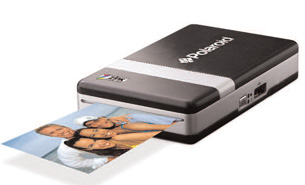
Mobile Photo Printer The first in a series of Instant Mobile Printers from Polaroid Corp. (Waltham, MA), the Pogo will also be the first commercial device to deploy ZINK inkless printing technology. Designed to be used with a cell phone or digital camera, the Pogo printer is approximately the size of a deck of cards and weighs 8 ounces with battery. According to Polaroid, the Pogo produces a 2- x 3-inch borderless full-color print in 60 seconds and prints dry-to-touch, waterproof, and tear- and smudge-proof images. A picture of simplicity, the Pogo has just two tri-color LED status lights: battery power and operational status. Packets of ZINK paper load through a top door, and prints exit through a side slot. The Pogo connects to digital cameras through a PictBridge USB cable and to camera-equipped phones wirelessly through Bluetooth. Its 7.2V rechargeable lithium-ion battery is good for about 15 prints per charge, and an AC power adapter provides virtually unlimited output. Polaroid expects the Pogo Instant Mobile Printer to appear in stores later this year and cost about $150. Ten-packs of ZINK thermally sensitive paper will be $3.99, according to the Polaroid. For information, visit polaroid.com/onthego. |

In our simulation, the medium was represented as a single uniform sheet with mechanical and thermal properties characteristic of the plastics used in the layered structure. We drew the properties of common materials from the COMSOL Material Library and that of the remaining materials from manufacturers, in-house measurements, and online resources like MatWeb.
The platen is a rubber-coated roller that presses the print medium against the heating elements. Since the heaters are on a curved glass surface and the medium is flat, it is a function of the rubber to promote “wrapping” of the medium around the heaters, thus ensuring good thermal contact. The moving medium and platen carry heat away from the printing region, providing supplemental cooling to the print head, beyond that of the heat sink.
Mechanical and Thermal Modeling
We used COMSOL Multiphysics to model the mechanical and thermal behavior of our direct thermal printing process and to postprocess the data. The mechanical simulation investigated the compressive contact between the platen and the print medium as well as between the medium and print head. To avoid interpenetration of these components, we used the Contact Pairs feature of COMSOL’s structural mechanics module.
We simulated a single heater of the print head (a narrow slice out of the entire width of the object). The mechanical constraint at the sides of this slice would be zero displacement normal to the boundary. COMSOL enabled us to conserve memory by setting the material properties to be orthotropic with a Poisson ratio of zero in the normal direction, which had the identical effect of holding the walls fixed.
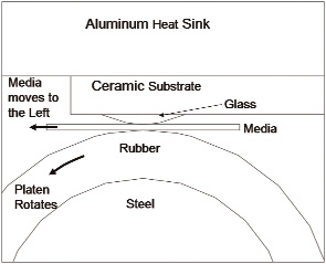 Figure 1: This illustration of the modelgeometry shows the relationship of featuresof the print head and the moving media. |
Our thermal simulation subjected the structure to periodic thermal pulsing of the heater elements. One problem was the thin layer of air in the vicinity of the contact between the heating element and the medium, which can develop poor mesh quality under compression. COMSOL let us omit this air layer and use extrusion coupling to communicate the surrounding material surface temperatures and positions across the gap. This allowed independent evaluation of heat flow through the layer.
Another concern was that both the media and platen move and transport heat. COMSOL helped us with this by letting us apply a linear convective term with the velocity of the medium and a cylindrical convective term with the velocity of the platen. To represent the medium entering the printer at ambient temperature and leaving warmer, we set a fixed-temperature boundary condition at the entrance and a convective boundary condition at the exit.
With these features in place, we ran a time-dependent thermal simulation with a pulsing heat source on the compressed geometry. We then processed our solution with COMSOL Script.
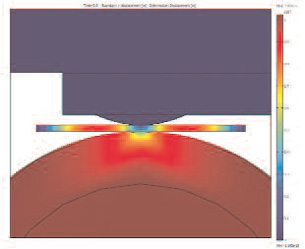 Figure 2: Mechanical compression of theplaten against themediumand print head(color corresponds to y-displacement). |
Postprocessing Crystallizes Concept
Our interest was in the temperatures in a crystal dye layer at a fixed distance below the heated surface. To find them, we needed to trace the time history of the temperature at points in the layer fixed to the medium. Since we used a convective term to simulate the media motion, the initial results were referenced to points fixed with respect to the printer, not the media.
The first postprocessing step resampled the data in a coordinate system moving with the medium. This was accomplished by recording the time-dependent simulation at evenly spaced time intervals, Δt, and post-interpolating the data with spatial intervals Δx of Δx=vmedium Δt. In this case, motion compensation corresponds to moving over by one spatial interval in the direction of motion at each successive time step.
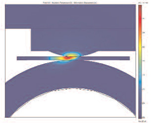 Figure 3: Temperature profile following a heatpulse. The color indicates temperature, witha scale going from 273° K to 315° K. |
With the time history of the temperature at each point in the layer, we applied a “media model” to determine the opacity of the dye activated at each point, thus revealing the shapes and positions of dots printed on a dye layer located at a hypothetical depth in the medium. Here, we considered a so-called “amorphochromic” dye developed specially for ZINK. This dye consists of colorless crystals that become colored instantly upon melting. Thus, a point in the medium that exceeds the melting point of a crystal will be colored in the final image. This makes the application of the media model a simple matter of comparing the temperature history of each point to a threshold melting temperature.
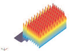 Figure 4: A surface plot showing themaximum temperatures reached at points ina 2D plane lying 3microns below the heatedsurface medium after it was heated with 3mspulses, spaced by 33ms. The temperature atthe peaks is 436° K (163° C). |
Figure 2 focuses on the distortion generated during the compressive stage of the calculation. The colors indicate the y-displacement of components as the platen pushes up against the media and the stationary print head. While the center and ends of the media remain relatively unmoved, intermediate sections move upward, illustrating the “wrapping” of the media around the heaters caused by the distorted platen.
The surface plot in Figure 3 shows the temperatures in the components following a thermal pulse and, as the system is cooling back to the heat-sink temperature, the heated media exits the printing region. It’s apparent that the print medium carries away heat (to the left), cooling the center of the heater. The platen also carries heat as it has risen in temperature.
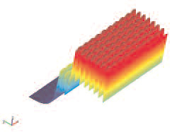 Figure 5: A surface plot showing the maximum temperatures reached at points in a 2D plane lying 30 microns below the heated surface. The peak temperatures in this case are 70° C. |
Postprocessed data (Figure 4) shows the maximum temperatures reached by an array points in a plane lying 3 microns below the heated surface of the medium after the medium is heated with 3ms pulses, spaced by 33ms. If you place a layer of color-forming chemistry at this depth in the medium and heat it, you get a regular array of colored dots. If you apply pulses of higher energy, temperature peaks rise and exceed threshold temperatures over a wider area, producing larger dots and increased color density.
The plot in Figure 5 shows the maximum temperatures reached in a plane 30 microns below the surface. Here, it is apparent that the temperature peaks are more diffuse due to the increased distance from the source of heat.
Figure 6 (left) compares the peak temperatures reached in planes that are increasingly far below the surface when the surface is heated with pulses that last 3.3ms and 16ms. The longer pulses supply more energy and produce a higher temperature. However, we can scale the power so that both pulses deliver comparable energy. In this case, the shorter pulses can produce relatively higher temperatures near the media surface and relatively lower temperatures internally than longer pulses of similar energy.
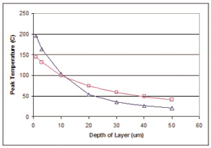 Figure 6: Comparison of the profile of peaktemperature as a function of depth for short(Δ=3ms) and long ( = 16ms) pulses ofheat. |
Our COMSOL simulations showed us how the temperature peaks diffuse away from the heat source. A comparison of the peak temperatures at various planes of the media indicated that we could produce bichrome images by intermixing short, high-power pulses and long, low-power pulses to melt crystals at different layers and with dissimilar melting points. With this knowledge, we knew we could position three dye layers to make a full-color medium and obtain photographic-quality images with one pass of the medium under the thermal print head.
Future Considerations
As a component of our ZINK thermal printing development, we make frequent use of COMSOL Multiphysics tools. Moving from product invention to product development, and then to manufacturing, we have touched on many engineering fields: mechanical, thermal, chemical, and fluid dynamics. The combination of all these fields in a single tool with a single user interface has lowered the barriers to using this type of modeling as a daily tool. And, with the first products incorporating ZINK technology now arriving on the market, our modeling will be guided by the imagination of our customers.
More Information:
COMSOL Multiphysics
Burlington, MA
comsol.com
MatWeb
Blacksburg, VA
ZINK Imaging, Inc.
Bedford, MA
William T. Vetterling is a research fellow and director of the Image Science Laboratory for ZINK Imaging, Inc., where Alexei Azarov is senior scientist, and Brian Busch and Chien Liu are distinguished scientists. Send comments about this article to [email protected].
Subscribe to our FREE magazine, FREE email newsletters or both!
Latest News
About the Author
DE’s editors contribute news and new product announcements to Digital Engineering.
Press releases may be sent to them via [email protected].


