

Latest News
April 1, 2006
By Jerry Fireman and Christoph Hiemcke
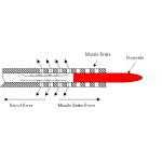
| One of the centerpieces of the Army’s Future Combat Systems (FCS) program is the development of new combat vehicles that are only about one-fourth to one-half the weight of the Army’s current vehicles, yet capable of mounting guns that as powerful as the older vehicle’s guns. To meet this goal, the new lighter vehicles require muzzle brakes that redirect part of the gun’s propellant flow backwards to reduce the gun’s recoil. But this redirection must be accomplished while keeping the blast overpressure on the vehicle itself low enough to prevent injury to nearby soldiers as well as damage to the vehicle. Testing proposed muzzle brake designs is expensive and time-consuming. The engineers at the Army’s Benét Laboratories in Watervliet, New York, have begun using CFD (computational fluid dynamics) to model the gun’s recoil forces and blast pressures for different muzzle brake designs to provide optimized solutions of low recoil force with acceptable blast overpressure. The key to their success in modeling blast overpressure has been the development and use of CFD software that automatically increases the density of the computational mesh in the area of the blast wave to provide the required accuracy, while keeping the mesh unchanged in other areas where the increased detail is not needed. With future code improvements, it is believed that this will help them get the accuracy they need, where they need it, without the expense of excessive computation times. Replacing a Fleet of Combat VehiclesThe FCS, the Army’s flagship transformation program, is a networked array of systems that use advanced communications and technologies to integrate the soldier with manned and unmanned platforms and sensors. The Army transformation requirements include the ability to put a combat-capable brigade anywhere in the world within 96 hours, a full division in 120 hours, and five divisions on the ground within 30 days. To meet this goal, FCS will, over time, replace the current fleet of heavy vehicles-Abrams tanks and Bradley Fighting Vehicles-with a new family of lighter and smaller manned and unmanned ground vehicles and aerial vehicles. ‹ ‹ Figure 1: Typical perforated muzzle brake operation as projectile passes muzzle brake holes and flow begins to act on the gun tube producing a force opposite of the recoil force. The maximum essential combat configuration weight for the FCS family of systems will be 19 tons. These lighter, smaller vehicles are designed to fit into a C-130-like plane. The C-130 is capable of landing on smaller and less-developed landing strips, making it possible to deliver more vehicles closer to where they are needed. The first FCS unit will be fielded in 2008, with 32 brigades equipped by 2014. The U.S. Army Armaments Research, Development and Engineering Center (ARDEC)‘s Weapon Systems & Technology (WST)/ Benét Laboratories is co-located at the Watervliet Arsenal in upstate New York. Benét has been assigned the responsibility for designing the muzzle brake of the Mounted Combat System (MCS) tank cannon and the Non-Line of Sight Cannon (NLOS-C) artillery cannon, which are designed to replace the Abrams tanks and Paladin artillery vehicles, as the Army’s primary fighting and artillery vehicles. The 19-ton MCS isn’t heavy enough to absorb the full recoil force of its gun, which fires ammunition that is as powerful as the 70 to 80 ton Abrams tank can fire. So the MCS will use a muzzle brake to reduce the recoil, a device that is analogous to the thrust reversers that are used to slow jet airliners after landing. The muzzle brake is a series of holes in the gun tube near the muzzle, through which the gas vents. The venting process pulls the tube forward to counteract the recoil (see Figure 1, above). Despite the advantages that it offers, simulation presents its own special challenges. The motion of the blast wave must be modeled through a large volume of space. Mesh sizes of 1/2 mm or smaller are required at the edge of the blast wave to accurately capture the short-lived transients. When the mesh is coarser than this value, it artificially spreads out the blast wave and reduces the accuracy of peak pressure predictions.
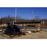
Having the mesh this fine throughout the entire solution domain, however, would increase the model size to the point where it would take too much time to solve, even on the fastest available computing hardware. Steady-state problems involving steep gradients, such as those occurring at shock fronts, are addressed by using a fine grid in one small region of the computational domain (that containing the most prominent gradients). In this case, however, the steep gradients associated with the blast wave rapidly sweep through the entire domain, so a novel approach is required to simulate the moving blast wave properly. To overcome this problem, Benét Laboratories is taking advantage of the easy to use dynamic adaption capabilities of FLUENT CFD software from Fluent. Dynamic adaption continually changes the density of the mesh throughout the domain so that as the blast wave propagates, the mesh in the surrounding area is made finer. Regions that were refined earlier in the calculation are coarsened to a reduced mesh density, if the conditions there no longer require the increased detail. FLUENT allows the user to select the criteria upon which the mesh is refined or coarsened. Adaption based on the absolute pressure level has proven most effective for Benét to date. Validation Case To validate the accuracy of the simulation, Benét engineers modeled a test rig at the Aberdeen Proving Ground consisting of the gun that will go into the MCS mounted on a stand (see Figure 2, above). The simulation was performed on a Linux Networx 32-processor cluster with Myricom’s Myrinet serving as the backbone and Metis handling load balancing. Engineers configured the zonal adaption capabilities of FLUENT to adapt the mesh every 15 time steps and to increase the number of elements in areas of high pressure by a maximum factor of 32. This simulation began at 1.7 million cells and increased to a peak of 34 million cells through adaption.
Comparing the simulation predictions to physical testing has shown that CFD accurately predicts the primary or first blast wave peak pressures. But the pressure history (see Figure 3, above) indicates that the CFD results for the peak pressures associated with the waves that are reflected from the ground are lower than the measured values. Furthermore, the shape of the pressure waves predicted by CFD is much gentler than their measured counterparts. A more finely resolved mesh would yield higher peak pressures and steeper waves, but there is always a tradeoff between accuracy and computational expense. For example, had this validation been performed with a significantly finer adapted mesh resolution—i.e., with a minimum cell dimension of 0.5 mm instead of 25 mm-engineers estimate that the calculation would have taken centuries, not days (see Figure 4, below). 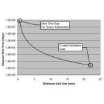 › › Figure 4: Chart shows how increase in mesh resolution to the ideal size would increase solution time to centuries with FLUENT 6.1.
But even without zone-based criteria, the CFD analysis via dynamic adaption was found to yield reliable results. With the model having been validated, Benét engineers are using it to evaluate alternative design configurations. The results of each simulation show peak pressure levels on the vehicle and can easily be animated to show the movement of the blast wave over time. This capability, which makes proposed changes easier to evaluate, will dramatically reduce the amount of time required to design the next-generation gun for the Army’s number one fighting vehicle. Jerry Fireman is the president of Structured Information, a technology consultancy in Lexington, MA. Christoph Hiemcke is a Senior Business Services Engineer for Fluent Inc., a CFD provider in Lebanon, NH. Send your comments about this article by clicking here. Please reference “Muzzle Brakes, May 2006” in your message. Editor’s Note: Dan Cler, Senior Mechanical Engineer, Benét Laboratories, Watervliet, NY, provided additional input for this article. Contact Details | |||||
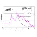 ‹ ‹ Figure 3: Validation case comparing FLUENT 6.1 results to experimental gun firing for the test rig shown above (Notes: *The type of pressure transducer used to acquire experimental data overshoots. It is known that the actual pressure is closer to what is indicated in the plot. **Reflected wave pressures are underpredicted by FLUENT due to lack of mesh resolution).
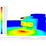
Subscribe to our FREE magazine, FREE email newsletters or both!
Latest News
About the Author
DE’s editors contribute news and new product announcements to Digital Engineering.
Press releases may be sent to them via [email protected].


