

Latest News
April 1, 2011
By Marc Horner, Ph.D.
To truly simulate how many medical devices will perform, design engineers must first simulate the environment those devices will perform in: the human body. In silico models predicting the in vivo performance of medical devices are becoming more and more prevalent across all biomedical sectors. The shift toward geometry derived from medical scan data is providing previously unparalleled understanding of device performance and patient safety.
Patient-specific geometry is only a local enhancement to the numerical model, however. In other words, this enhancement does not provide any information regarding the dynamic and compartmental responses of various organ systems to the presence of foreign objects or external stimuli. Therefore, a global perspective must be adopted if we want to truly understand device performance. Human body models (HBMs), can address this critical need.
The use of HBMs is enabled by:
- Our understanding, and thus our ability to mathematically describe, the human body is to the point where we can assemble lumped parameter human body models as “boundary conditions” for biomedical simulations.
- Improvements in ease-of-use and stability of multi-physics modeling tools.
- The continuing increase in computational capabilities.
The first bullet is critical to the success of HBMs. The human body is a complex system that is impractical to model explicitly at this time. Therefore, one must make some simplification to include macro-effects. The most straightforward simplification is to use lumped parameter representations of the human body coupled to detailed 3D analyses.
System level modeling tools can be coupled to traditional mechanical (finite element analysis), fluid flow (computational fluid dynamics) and electromagnetics modeling software to incorporate the loads and boundary conditions applied by the human body.
Types of HBMs
HBMs fall into two general categories: lumped parameter models and geometrically accurate models. Lumped parameter models provide boundary conditions or loads that act on the boundaries of the computational domain. Examples of lumped parameter HBMs include electrical circuit based (Windkessel) models of the circulatory system, pharmacokinetic models of drug absorption and clearance, and lumped parameter models of the musculoskeleton.
Highly accurate geometric models are the second class of HBMs. They are reconstructions of the human body down to a predetermined length scale. Geometric models are primarily used to understand the interaction between the human body and electromagnetic fields. An implanted device may or may not be present.
HBMs can be used to improve the accuracy of medical device simulations. For example, HBMs enable a designer or analyst to more accurately predict:
- Blood flow around implanted cardiovascular devices.
- Plasma concentration of a drug delivered from a transdermal patch.
- Loads on orthopaedic implants.
- Heating of tissues or an implant during a medical scan.
HBM coupling to traditional modelling tools is needed to understand the safety and efficacy of medical devices.
|
Arterial HBMs
Arterial flow models are useful for predicting blood flow patterns after implanting a device, such as a stent, and for understanding the flow patterns in various diseased states, e.g. the circulation patterns that occur in a cerebral aneurysm. One complicating factor in arterial flow modeling is the application of accurate outflow boundary conditions. Specialized boundary conditions are required because the flow split at a bifurcation is a function not only of the bifurcation geometry, but also the structure and state of the downstream vasculature. Without a specialized outflow condition, a designer will not have a proper understanding of the baseline flow patterns and how an implanted device will impact those patterns.
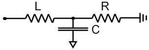
Arterial HBMs discretize the vasculature into a network of short segments. Each segment is represented using an electrical circuit or 1D flow equation. The fully discretized system predicts the flow rate and pressure in each segment. One of the more common electrical circuit representations is the 3-element Windkessel (WK) model. It represents inertial losses using an inductor (L), pressure losses with a resistor (R), and vessel compliance with a capacitor (C). The circuit is identical throughout the arterial tree, but the RLC values vary to account for physiological and structural changes, e.g. compliance dominates at the aortic root while pressure losses are more important in smaller vessels.
Figure 1 summarizes a validation case of the arterial HBM. The model consists of the 3-element WK condition applied at the outlets of an idealized abdominal aorta. The geometry and boundary conditions were symmetric in this case, therefore only half the geometry was modeled. A transient inflow waveform was culled from a literature source. ]1] Blood flow rates and pressure drops were modeled in ANSYS FLUENT. The results for the outlet pressure (Pout) show excellent agreement with the pressures reported in ]1]. And more importantly, Pout now varies between physiologically relevant values, and the curve has a physiologically realistic shape. Neither of these would be predicted by standard (constant pressure) outflow conditions.
Figure 1: Validation of the 3-element WK model with data from reference (1). |
 Pharmacokinetic model |
Drug Delivery HBMs
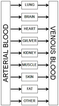
Pharmacokinetic (PK) models are the HBMs for drug delivery. The PK approach assumes the body can be treated as a collection of well-mixed chemical reactors. Rate constants for each reactor establish drug absorption, distribution, metabolism, and excretion rates. With appropriate parameters in place, we can predict the time course of drug concentration in the plasma and other compartments, which helps establish bioequivalence for regulatory approval.
A transdermal patch is one example where PK can help establish that the device and formulation meet clinical requirements. Figure 2 shows an example of a transdermal patch coupled to a three-compartment PK model. The patch model was initially validated against the experimental results of Rim et al. ]2] In their model, the drug diffuses through the patch and skin until reaching the far edge of the epidermis. A permeation enhancer was included in the formulation, which modifies either the drug diffusivity or drug solubility in the skin layer. There was no PK model in their experimental setup. The results in figures 2b and 2c show excellent agreement between the Rim et al. results and the ANSYS FLUENT model.
We then coupled the validated drug transport model to the three-compartment PK model shown in Figure 2a and simulated the delivery of the analgesic fentanyl over several days. The results for drug flux and plasma concentration show the rise and fall of the drug concentration in plasma after each application (see figures 2d and 2e). Adding PK thus provides the full understanding of how design and formulation affect drug delivery.
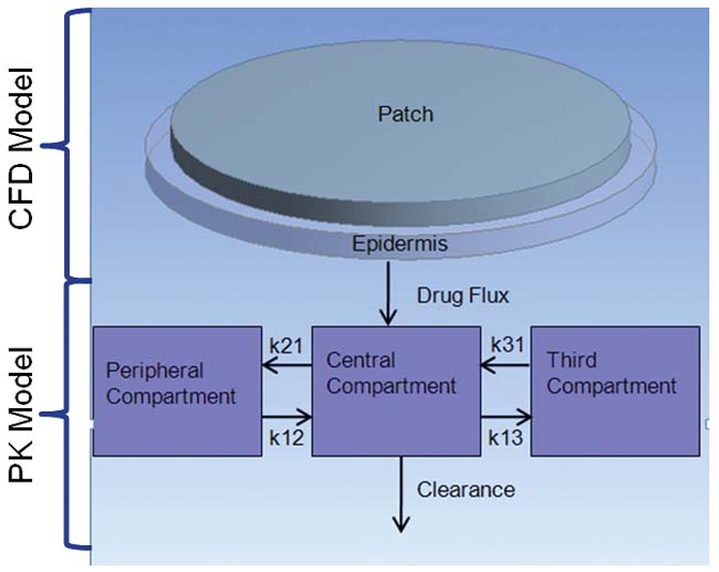 Figure 2a: Transdermal patch and skin model shown coupled to a PK model. |
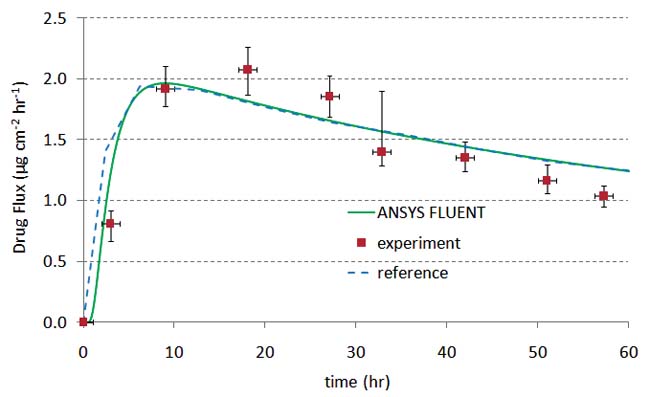 |
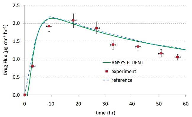 Figure 2b and 2c: Validation of the transdermal patch model against the experimental and computational results of Rim et. al.(2) |
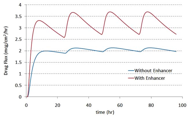 Figure 2d: Fluxconcentration over a period of 96 hours (new patch applied every 24 hours). |
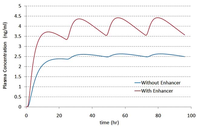 Figure 2e:Plasma concentration over a period of 96 hours (new patch applied every 24 hours). |
 Musculoskeletal |
Musculoskeletal HBMs
Musculoskeletal (MSK) HBMs are multi-body dynamics tools that predict muscle and joint reaction forces and inertial loads encountered when the body is in motion. MSK models are comprised of hundreds of muscles that are fixed at their respective attachment points. The mechanical behavior of each muscle is modeled as a parallel circuit comprised of three elements: a spring in parallel with a spring and activator element.
The resulting strength of the muscles is highly nonlinear, both with respect to elongation and accelerations. Simulations can be based on patient-specific data such as anthropometrics, strength, bone geometries and muscle attachment points. When coupled to FEA, MSK models can be used to predict the risk of osteoporotic fracture, predict forces and moments acting on an implant, and for surgical planning, to name only a few applications.
An example of a patient-specific workflow that uses the results of inverse dynamics is shown in figure 3. This figure shows the extraction of a patient bone from medical scan data, the derivation of joint motions and loads from a walking cycle, and the application of this information to a femur and acetabular implant.
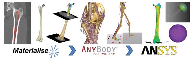 Figure 3. Patient-specific analysis of the stresses on a hip implant and femur under walking conditions. (a) medical scan; (b) segmentation in Mimics; (c) walking gait cycle from the AnyBody Modeling System; (d) combination of geometry and load data into ANSYS Mechanical simulation of stresses on the implant and bone |
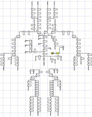
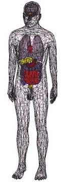 Geometrically of the arterial system of drug metabolism model accurate HBM |
Electromagnetic HBMs
Electromagnetic safety standards establish exposure limits for humans to radiofrequency (RF) fields. These standards are established by national government. Limits are expressed in terms of power density and specific absorption rate (SAR). Power density quantifies the intensity of exposure and SAR represents the power that is actually absorbed by biological tissue. The last class of HBMs, geometrically accurate HBMs, are critical to establishing the electromagnetic safety of wireless technologies, diagnostic medical equipment, and therapeutic treatments. This is driven by the need for the manufacturer to have a good understanding of the distribution of absorbed energy by the various tissues of the human body.
Geometrically accurate HBMs are comprised of various anatomical structures down to a predefined accuracy. Each object has associated frequency-dependent material properties that govern how the electromagnetic field propagates locally and how much power is absorbed. The latter is essential, because absorbed electromagnetic power is converted to heat. This forms the rationale for the aforementioned safety standards.
|
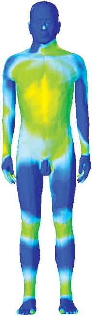
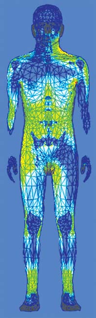
The ANSYS HBM is available in 1, 2, and 4 mm surface accuracies. The coarser models are useful when users want to save computer memory and simulation time. The level of detail is also adequate at not-very-high frequencies, when the wavelength is long. Figure 4 illustrates how the material properties affect the propagation and absorption. In Fig. 7a, note the blue and green bands on the legs. This indicates that there is a standing wave. The wavelength of this standing wave is several times shorter than the free-space wavelength for this particular frequency (64 MHz). This is a direct consequence of the material properties, specifically of the relative electrical permittivity. In Fig 4b, note the different absorption rates for muscle and bone. The kneecaps, shinbones and hips stand out in blue, having a much lower absorption rate than muscle and organs. Again, material properties are the key player. This is because the water content of bone is much lower than that of the muscle and organs, leading to a lower electrical conductivity.
A second example requiring geometric HBMs is planning a patient-specific hyperthermia treatment. Hyperthermia is a non-invasive treatment that heats a tumor using a phased-array applicator, essentially an antenna. The benefits of hyperthermia include starving tumor cells of vital nutrients and increasing the therapeutic effect of the chemotherapeutic drug. The challenge is to apply the right amount of power to the tumor while minimizing the amount of power delivered to healthy tissue. Side effects, such as burns, blisters, or pain, are thermal in nature and can be minimized through a priori numerical simulations.
Figure 5 outlines the planning process using the ANSYS HBM as a template. First a tumor is introduced into the femur, which is then analyzed for the amount of power delivered using ANSYS HFSS. The electromagnetic losses are passed from ANSYS HFSS to ANSYS Mechanical for a transient thermal analysis. Pennes’ bio-heat transfer equation, a correlation that establishes the rate of heat transfer between tissues and the flowing blood ]3], was also implemented as a sink term in the thermal model. The SAR calculation results (Figure 5b) are passed to ANSYS Mechanical for the transient thermal calculation (Figure 5c). And as shown in figure 5d, the tumor temperature predicted in by the multi-physics simulation agreed very well with experimental values. ]4]
Figure 5. Coupling ANSYS HFSS to ANSYS Mechanical to plan a hyperthermia treatment.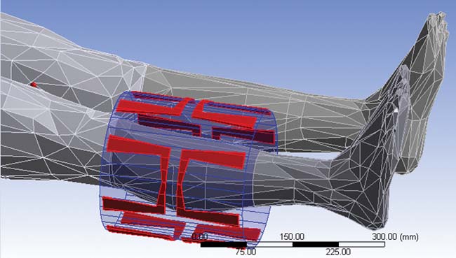 (a) Leg portion of the ANSYS Human Body Model |
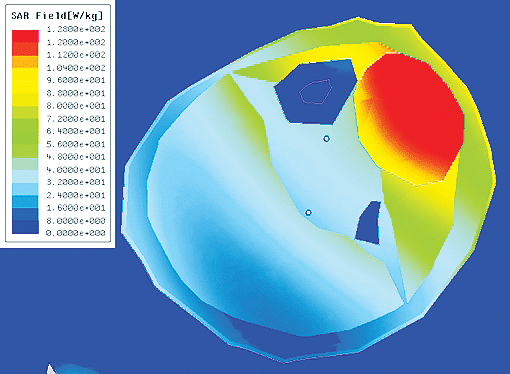 (b) Local SAR with optimized array weights (performed in HFSS) |
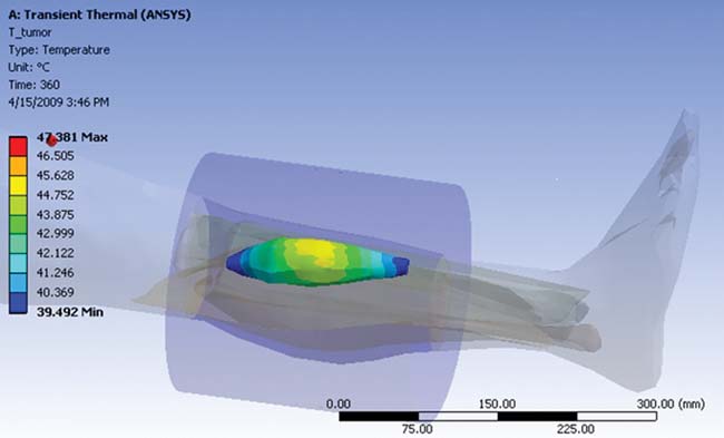 (c) Thermal analysis of tumor heating (performed in ANSYS Mechanical) |
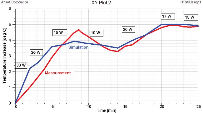 (d) Time evolution of the tumor max/min temperatures |
In conclusion, a holistic approach is required for biomedical research and development because the device, drug, or other treatment interacts with human body systems. Lumped parameter models are a practical solution because of their relative simplicity, allowing the designer to further refine their technology to work together with the human body. These models are accurate enough to be used today.
INFO
ANSYS
AnyBody Technology
Materialise
REFERENCES
]1] Wan et al. A one-dimensional finite element method for simulation-based medical planning for cardiovascular disease. Comput Methods Biomech Biomed Engin. 5 (2002) 195-206.
]2] Rim et al., Finite element modeling of coupled diffusion with partitioning in transdermal drug delivery. Ann Biomed Eng. 33 (2005) 1422–1438.
]3] Calonius O and V Saikko. Slide track analysis of eight contemporary hip simulator designs. J Biomech. 35 (2002) 1439 “1450.
]4] Pennes HH. Analysis of tissue and arterial blood temperatures in the resting human forearm. J Appl Physiol 1 (1948) 93-122.
]5] Zhen et al. Towards the validation of a commercial hyperthermia treatment planning system. Microwave J. 51 (2008) 28.
Marc Horner is a Lead Technical Services Engineer at ANSYS, Inc., who focuses on the healthcare industry. This article included contributions by AnyBody Technology (Aalborg, Denmark), and Materialise Inc. (Leuven, Belgium).
Subscribe to our FREE magazine, FREE email newsletters or both!
Latest News
About the Author
DE’s editors contribute news and new product announcements to Digital Engineering.
Press releases may be sent to them via [email protected].


