Helping design and engineering professionals discover, evaluate and specify technologies and processes that shorten the design cycle and enable success.

May 2026 Special Focus: Artificial Intelligence in Design and Simulation
In this Special Focus Issue, learn about the latest developments in the integration of artificial intelligence into engineering workflows.

April 2026 Special Focus Issue: Generative Design
In this Special Focus Issue, Digital Engineering takes a look at how generative design solutions can be used across different types of design problems and with a variety of manufacturing approaches to accelerate design space exploration, and…
The mold and die industry gets a lot of attention from software developers. When you look at the global market for product development and manufacturing software, mold and die is one area that seems to get an inordinate amount of technology and applications devoted to it. Whether that’s due to the shear scale of tooling-based manufacture, the complex of the process, or simply the need to get the job done quickly—I’m not too sure. One of the leading developers that concentrate on the mold and die process is Cimatron, an Israeli developer founded in 1982 and with subsidiaries throughout Europe, Asia, and the U.S.
The basic premise behind CimatronE is to provide an environment to handle all of the processes, workflows, and individual stages of taking a part through to tooling production and manufacture. It’s a fully integrated, end-to-end solution that includes modules for design, moldmaking, electrode design and manufacturing, reverse engineering, drawing, and NC. There’s even a footwear module.
So, let's step through CimatronE and its areas of operation and see how it benefits the mold and die user.
Automated and Manual Tooling
The starting point for the vast majority of projects is the receipt of the part data from your client. As you’d expect with a system aimed at the subcontractor market, CimatronE allows you to import and deal with a wide range of data formats ranging from IGES, STEP, ACIS, and Parasolid, as well as native formats, such as CATIA and Pro/Engineer. As we all know, this is often a problematic process, so CimatronE also includes an assortment of tools to handle the problems inherent in any data exchange, such as automated healing tools, as well as more manual capabilities should you need to dive in and fix problems by hand. Once your part data is in a workable form, the tooling design process can proceed.
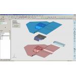
› › Once your client’s data is imported and repaired, Cimatron takes your data and assists in developing the split line, face assignments, and the basics of additional actions, such as slider and lifters.
The first stage is to define the part split. At pretty much every stage, CimatronE has a range of semi-automated tools that can handle each process or task—called Process Wizards. If your part geometry is simple, then the split definition is going to be similarly simple. But as soon as you start to require something more complex such as shut-offs and sliding mechanisms, you can then either use additional Process Wizards or dive in and use the extensive modeling tools to create the forms manually. What is important is that CimatronE provides you with tools that automate all manner of the processes, such as parting line and surface creation, core and cavity split but, should you need to, you can manually create the geometry using well-developed 3D modeling tools.
Mold Base Design
The next step is to take that core, cavity, and basic elements for any mechanisms forward into the mold base design process. At a core level, the mold base development tools are built onto the standards catalogs from the major global suppliers as well as some regional ones, including DME, DMS, Hasco, Futaba, Misumi, and Strack (among others).
The mold base development process works through it in a logical manner, from defining your preferred suppliers, selecting configurations (in terms of plates and moving components), then specifying the mold base. CimatronE has a lot of intelligence built in and can handle much of the mundane, repetitive work involved in this process automatically, but with the control.
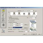
‹ ‹ The Mold Base wizard steps you through the selection of a component supplier, the mold base, mold plate orientation and configuration, and the insertions of standard components.
For example, when you’re looking at plate sizes, CimatronE only presents you with selections from the chosen catalog that conform to yourseries or supplier select and that can accommodate the bounding box size of the core/cavity block you’ve already defined (including a user-definable clearance value). This might sound like a small thing, but when you’re looking at potentially thousands combinations of products, an intelligent filter is going to help. Also, CimatronE will automatically (if you want it to) add standard components like leader pins and bushings, locating pins and sleeves, screws, and spacers where required.
Intelligence Adapts to Usage
Once the basic mold base is complete, the real work begins as you adapt that starting point to the core and cavity and add the various features that make it a functional mold. As with other areas, CimatronE includes a number of wizard-driven Process Guides to step you through some aspects such as runner and gating, ejector systems, cooling channel and slider/lifter mechanism design, and you’ve got the backup of the modeling tools should you need it.
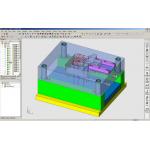
› › This screen shot shows a mold base under development, with slider mechanism in place, cooling channels positioned, and the mold plates adapted to carry the core and cavity—as well as the ejector system.
An excellent illustrative example of how CimatronE adds intelligence to the process is the cooling design process. Again, it’s a Process Guide that steps you through the procedures. To start, you sketch out the horizontal and vertical sections for the circuit in wireframe using the standard wireframe tools, and then start to flesh it out in 3D.
Of course, once your basic circuit is in place, the next stage is to add the associated components, such as o-rings, adapters, baffles, plugs, and nipples that move it from being pure geometry to something more meaningful in a manufacturing context. The components are catalog-based and intelligent, so they adapt the surrounding geometry to accommodate for their use by adding clearance holes, counter bores, etc. Even the nipple components, when set back into the mold plate, include a counter-bore that will accommodate the appropriate spanner from the supplier.
 /div>
/div>
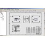
‹ ‹ CimatronE adds process and industry knowledge to a core level of 3D modeling and 2D documentation and annotation tools. Here, assembly drawing views can be adapted in each instance to show specific groups of components - a requirement perhaps unique to the tooling market. Click image to enlarge.
Once the mold base is complete, you then take it into the drafting and documentation process. As you’ve probably gathered, CimatronE has been developed to support the industry-specific needs of its users, so the drafting tools cover all of the usual bases, for drawing view layout, dimensioning and annotation, bill of material extraction, as well as some specialized capabilities. And example of the latter is to select which mold components are displayed in each drawing view, then derive another drawing view from first view but have it display a separate set of components. In general-purpose modeling tools, the derived view would retain the same component display state; within CimatronE, you can adapt each view to your own requirements.
Conclusions
Alongside the core mold and die design tools, CimatronE is rapidly expanding into other areas of the tooling-related production environment. We don’t have room to talk about the electrode design and manufacture tools, the CNC programming technology (which covers basic 2.5-axis machining through to control over state-of-the-art 5-axis machines), tools for the progressive die market, or the emerging world of micro milling.\
What should be clear is that CimatronE has been developed with a very specific user community in mind. Yes, that community is expanded, but the core values in the system remain—providing an environment in which users can conduct their work efficiently, taking advantage of process guidance and automation where necessary.
But alongside this, CimatronE also provides tools that allow that user to delve into the geometry and fix problems, solve issues, and create the custom geometry that often presents the moldmaker's art. If you’re in the mold and die market, then CimatronE is a cracking system worthy of more than just a cursory glance.
Al Dean is Technology Editor of the UK's leading product development and manufacturing journal, MCAD and is Editor of Prototype, for the rapid prototyping and direct manufacturing industry, both available by clicking here. Send your comments about this article through e-mail by clicking here. Please reference "CimatronE, April 2006" in your message.
Product Information
CimatronE 7.0
Cimatron Technologies, Inc.
Novi, MI

DE's editors contribute news and new product announcements to Digital Engineering. Press releases may be sent to them via [email protected].
Follow DEJoin over 90,000 engineering professionals who get fresh engineering news as soon as it is published.


About Us · Contact Us · Editorial Team · Advertising · Privacy Policy · Subscriber Services · © 2026 Digital Engineering 24/7 · Peerless Media