

Latest News
June 1, 2006
By Al Dean
Modeling the power, drivetrain, control, and mechanical systems of hybrid electric vehicles for optimal performance.
Hybrid electric vehicles (HEVs) have the potential to substantially improve fuel economy and reduce the polluting emissions associated with the internal combustion engine (ICE). But designing HEVs can be a complicated task.
Because HEVs combine an electric drive with a conventional ICE as part of the automobile’s powertrain, the vehicle’s kinetic energy can be captured during braking, transformed into electrical energy, and then stored in the battery. Designing such a system requires an accurate and complete model of the power, driveline, mechanical, and control systems, including power management control algorithms that optimize fuel economy and performance. The vehicle power systems and driveline assemblies can then be simulated with the control strategies. One effective way to do that is to test controller hardware in a real-time simulated environment that approaches operational system behavior by using hardware-in-the-loop simulation.
Finite element analysis (FEA) and 3D multibody simulation are limited in their usefulness for designing HEVs. The detail in system geometry is beneficial but time-consuming, and is usually introduced late in the design process. Specialized software programs used to model ICEs or electrical motors are good for optimizing single systems, but less useful where electrical circuits and mechanical components need to be modeled together. Another alternative is to simulate the design by deriving and solving the dynamic governing equations, but this can prove difficult as the number of degrees of freedom grows.
› › Designing hybrid electric vehicles is a complicated task that benefits from a unified graphical modeling system. In this model, Simulink represents the HEV Powertrain with a schematic showing the connection between the system components, including gasoline engine, electric drive, battery and transmission.
Due to these limitations, most HEV development has used prototypes to test performance before changes are made based on results. This is time-consuming and expensive, often forcing engineers to make decisions after evaluating only a few of the alternatives.
Next-generation control design software, such as the Simulink family of products from The MathWorks, provides a unified graphical modeling environment ideal for HEV model-based design. Pre-configured automotive-specific component models handle all elements of the HEV, including power, driveline, mechanical, and control systems. Engineers can use pre-built primitives, advanced algorithms, incorporate their own C-code, rapidly modify and evaluate the model, and view performance results. Optimization routines support specific objectives, such as maximizing fuel economy, and engineers can easily convert the model to a real-time simulated environment to evaluate system performance before moving ahead to build costly prototypes.
Building High-Level HEV ModelsThe ability to model all subassemblies means that a model can include just enough detail to address the high-level design issues that must be resolved early. Later in the process the model can be expanded to address more detailed design decisions.
In this example, engineers began by building a module that represents the actions of a driver in a simple sequence using the major systems of the HEV: accelerating under full throttle for 30 seconds, backing off the throttle, coasting for 10 seconds, and then braking for the final 20 seconds.
The simulated HEV uses a permanent-magnet DC-type electric motor modeled with two terminals where voltage is applied, a shaft that delivers torque to the driveline, and an electric circuit containing a resistor, an inductor, and a back-emf (electromotive force) load. The torque exerted by the motor is proportional to the current driven through the circuit. The model calculates the current based on the voltage and circuit characteristics. The back-emf load applies a voltage to the circuit that is proportional to the shaft speed and, in general, opposes the voltage provided by the power source. At top motor speed, the back-emf voltage counters the power source voltage perfectly to balance the circuit with no current flow.
The motor can also act as a generator to charge the battery using the back-emf voltage. This is not as simple as it sounds. During typical vehicle operation the back-emf voltage is less than the battery voltage, which means that there is no driving voltage to push current into the battery. To charge the battery, a hardware device called a two-quadrant chopper (built with transistors and diodes) rapidly opens and closes a switch between the motor terminals. The effect creates voltage pulses across the motor inductor that are powerful enough to drive current flow back into the battery.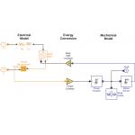
‹ ‹ The electric motor model combines the schematic description of the electric circuit (in orange) with a mechanical description of the shaft and its connection to the powertrain (in blue).
The combustion engine is modeled by defining the relationship between the throttle position, velocity, and torque. The ICE and electric motors connect to a planetary gear that combines their power to drive a differential that controls the rotation of the two front axles. Two clutches are used to connect and disconnect the two power sources from the driveline. This parallel HEV configuration enables a wide range of combinations of the ICE and electric motor. The clutch is defined to model both the dynamic and static friction states that occur as it transitions into full engagement.
The control system is configured so that the vehicle operates on the gas engine only until the wheel axle reaches a speed of 100 rpm. At that point, both the ICE and electric motor drive the vehicle. The output of the simulation shows a little kink in the velocity-versus-time curve, indicating an acceleration when the electric motor is connected to the driveline. This simple model can be used to improve the amount of energy recovered by the battery during braking. Engineers can change the frequency of the two-quadrant chopper signal and see what proportion of the electrical power consumed during the simulation cycle was recovered. In one typical example, engineers increased the proportion of recovered energy from 10 percent to 40 percent.
After the first iteration, engineers can refine the design and perform further optimizations. For example, they can add tire and road interactions, wind resistance, or hill climbing and descending to provide additional sources of energy exchange. Such an extension of the model might require use of full multi-body dynamics tools, such as the Simulink add-on product SimMechanics. In the Simulink environment, mechanical blocks can be connected to driveline blocks, electrical power system blocks, and control systems blocks to incorporate all aspects of the design into a single simulation.
By eliminating the need to transfer data between programs, engineers can perform far more design iterations in a given amount of time. Accuracy is also improved because the single simulation system avoids the introduction of errors that often occur at the interface between different modeling environments.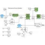
› › The Simulink model illustrated above accounts for the hybrid electric vehicle’s use of a planetary gear system to converge the power provided by the gasoline engine and the electric drive.
Optimization routines can be incorporated within the same environment to automate the process of choosing electrical, mechanical, and controller design parameters for purposes such as maximizing fuel economy while maintaining acceptable performance and range. These routines are available in Simulink through its integration with MATLAB. The MATLAB product family provides algorithms that solve constrained and unconstrained continuous and discrete problems, as well as functions for linear programming, quadratic programming, nonlinear optimization, nonlinear least squares, nonlinear equations, multi-objective optimization, and binary integer programming. They enable engineers to find optimal solutions, perform tradeoff analysis, balance design alternatives, and quickly optimize methods in algorithms and models.
After designing the controller algorithm, it is time to test the software implementation on the production embedded processor. C-code can be generated directly from the controller model and run on a rapid control prototyping system to produce a prototype of a control algorithm or on a production embedded controller. For example, Real-Time Workshop and Embedded Target for TI C2000 DSP from The MathWorks provide fixed- and floating-point code generation from Simulink for TI C2000 DSPs. Similar targets are provided for many other processors. The control prototyping system can be used to operate a prototype of the HEV.
In most cases, however, engineers will want to test the code long before they have access to an HEV prototype. Hardware-in-the-loop simulation addresses this need by providing an alternative testing capability using a simulated plant model. This way engineers can test their control software on embedded hardware (or an equivalent prototyping system) using a real-time simulation of the HEV plant and its operational environment, even before the HEV prototype can be built. The simulation uses the same I/O interfaces to connect the embedded processor to the simulated plant that would be used to interface to the actual physical plant. Simulated inputs and display of results test the operation of the models. Automatic code generation is used to convert the plant model to real-time executable code for hardware-in-the-loop testing.
Model-based design offers dramatic benefits to engineers designing HEVs and other complex products in which mechanical, power, driveline, and control systems interact. In the past, engineers needed to use separate modeling environments for each system, which meant that overall product performance could not be optimized or even evaluated until the prototype stage, a point when changes are expensive and can delay the delivery schedule.
Engineers can now accurately describe and simulate HEVs and other complex products at whatever level of detail is required. These models can be automatically converted into efficient C-code for hardware-in-the-loop simulation. This approach makes it possible to deliver higher product performance by evaluating many more design alternatives while reducing engineering costs.
Terry Denery joined the The MathWorks in 2004 and focuses on physics-based modeling and simulation tools. He has degrees in chemical and mechanical engineering from the University of Virginia and a Ph.D. in aeronautics and astronautics from Stanford University Send your comments about this article through e-mail by clicking here. Please reference “Real-Time HEVs” in your message.
Product Information
Simulink
The MathWorks, Inc.
Natick, MA
Subscribe to our FREE magazine, FREE email newsletters or both!
Latest News
About the Author
DE’s editors contribute news and new product announcements to Digital Engineering.
Press releases may be sent to them via [email protected].


