Helping design and engineering professionals discover, evaluate and specify technologies and processes that shorten the design cycle and enable success.

At the end of 2013, InformationIsBeautiful.net published an infographic showing how many lines of code are in the well-known apps, devices and products we use every day. As its basic unit of measure, the widely circulated chart used 1 million lines of code (the equivalent of 18,000 printed pages of text, or 14 times the length of Tolstoy’s War and Peace). The Chevy Volt electric car, for example, has 10 million lines of code. That’s not as much as the Boeing 787’s 14 million or the F35 fighter jet’s 24 million. But even those numbers can’t match the content of an average high-end car’s software, estimated to be 100 million lines of code -- far more than the 61 million lines powering Facebook.
The explosion of software code in products is a direct consequence of manufacturers’shifting emphasis from mechanical to electrical functions. To reduce the number of mechanical parts, which are costly to produce, with integrated circuits or Systems on a Chip (SoCs), engineers and designers must rely on software-driven operations. In turn, the shift encourages designers to explore more miniaturization and simplification opportunities through the use of SoCs on PCBs.
For future engineers, the embedded microprocessors and control software are an integral part of product design. It’s a trend to which the current crop of mechanical CAD (MCAD) and product lifecycle management (PLM) products is seeking to adapt.
For example, Bill Boswell, senior director of partner strategy for Siemens PLM Software, participated as a judge in the recent EcoCar 2 competition, aimed at encouraging next-generation engineers to design energy-efficient vehicles.
“On those teams, there are kids working on control systems, antilock brakes, and so on,”he points out. “For them, the control software is as much a part of the design as the brake pedal is.”
“I was required to take several classes on C++ programming and other programming courses to understand the relationship between hardware and software design,”he recalls. “In my program, the focus was still more on digital IC design; today, engineers need to think at the system level. Coding has always been part of engineering, but the dependencies have grown larger now.”
For products in automotive and aerospace, the complexity of what the embedded SoCs must do is increasing.
“There are so many dependencies in the system, because all these devices are talking to one another. When the Internet of Things (IoT) becomes widespread, SoCs and the software that goes into it will become even more complex,”Mandavia predicts. “The more functions we put on the SoCs, the more code we’ll have. There’s a direct correlation.”
John Winter, mechanical engineering manager for radio frequency (RF) equipment maker Bird Technologies, provides a historical perspective. “Eight years ago, we had two programmers,”he says. “Today, we have eight in my department, about 12 total in the company -- that’s around 40% of our engineers.”
Winter describes his firm’s typical workflow: “The mechanical designer will give the contractor [hired to develop the PCB design] the board outline, mounting holes and connector placements. The contractor would give us back the design so we could place it in our assembly to check placement. Then we give the green light to buy the board. Sometimes the contractor tells us how much room they need; sometimes we tell them how much room they have.”
In refinement of existing products, the established form factor (especially the chassis) limits the room available for the PCB. But in new product development, Winter acknowledges the board design tends to take precedence over mechanical considerations.
“The electrical engineers will get the board working first, in whatever shape they see fit,”he explains. “Then, when it’s ready, they’ll begin the back-and-forth process with mechanical engineers.”
The competition for space on the PCB itself is also fierce. John Isaac, director of market development for Mentor Graphics, compares the shrinking of PCB physical space and the increase of circuits on the board to “putting 10 lbs. in a 5-lb. bag.”
“What used to be a processor surrounded by 10 memory chips is now one integrated SoC,”he adds. “That’s going from 11 components to one.”
Zuken’s Mandavia agrees. “Talk about tug of war, things are getting very tight,”he says. “Now we’re trying to put the SoCs inside the substrate of a PCB.”
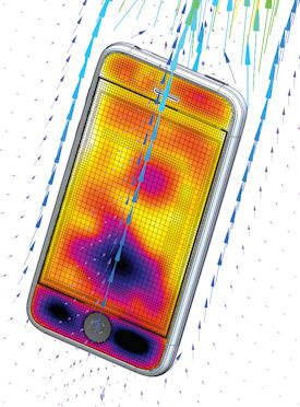 The increased density of PCBs generates significant heat gain. Thus, managing the heat in consumer products like smartphones is critical. Image courtesy of Mentor Graphics.
Heat management is becoming a big issue, says Mentor Graphics’Isaac: “As the SoCs fitted on the board are getting tighter, you have very hot components getting closer and closer to one another, housed in very small factors like cellphones and tablets.”
Even if the ECAD components are causing the heat, both the creation of the product’s top-level assembly (represented in CAD) and thermal analysis typically fall into the responsibility of the MCAD user. Thus, the mechanical engineer will feel the heat, so to speak.
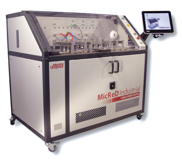
Mentor Graphics offers T3Ster hardware and software for testing and verification of SoCs and PCB packages. The thermal output from this can be imported into FloTHERM, a computational fluid dynamics (CFD) software package for simulation and analysis of board component behaviors. This allows the designers to simulate the behavior and interactions of the chip with the end product -- while the product is still in development and only exists as a digital 3D model.
Winter points out that the Super Video Graphics Array (SVGA), a computer display unit, is a critical component in Bird Technologies’products -- and thus a critical factor in design. “It has a microchip on it, so the mechanical engineers have to manage the heat from it,”he explains. “We need to position it in a way that let the heat escape through the chassis, or with fans and heat sinks.”
If the heat increases beyond what’s recommended by the chip maker, the chip’s performance itself begins to degrade, Winter says. He and his colleagues use Siemens PLM Software’s Solid Edge with Synchronous Technology (SE with ST), a direct-editing program, to design their RF devices. Unlike a history-based parametric CAD package, SE with ST lets designers quickly execute geometry changes without having to retrace the historical steps required to create the geometric features. That flexibility, Winter points out, is favorable to the iterative MCAD-ECAD back-and-forth workflow to negotiate the PCB’s space envelope and location in the product.
As Zuken’s Mandavia observes, “It’s great to be able to put all these functions on a single package or a chip, but now you have to think about its thickness and placement inside the product.”To that end, some ECAD developers like Zuken have begun working on accommodating 3D geometry transfer between ECAD and industry standard MCAD programs -- what Zuken calls “3D ECAD/MCAD co-design.”
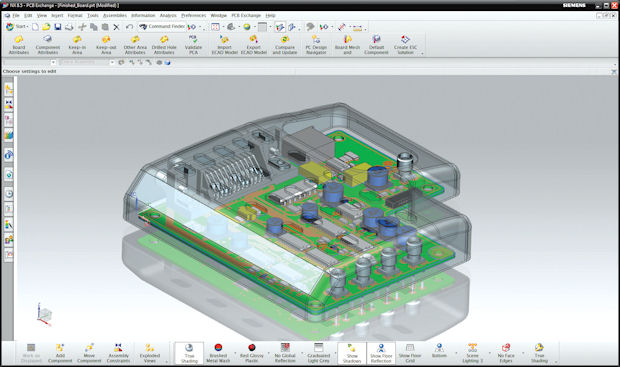 As MCAD and ECAD users work to define the PCB’s space in the assembly, it’s essential that they have a way to display the complete PCB model with conductive data inside the MCAD environment. This image shows a PCB design with enclosure within Siemens NX CAD program, a workflow made possible by Zuken. Image courtesy of Zuken.
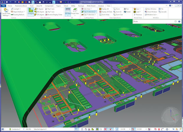 A PCB model with conduct placement and routing with accurate 3D mechanical constraints, as seen in Zuken’s CR-8000 PCB design program. Image courtesy of Zuken.
Zuken’s CR-8000, CR-5000 and CADSTAR products, Mandavia says, can export not only the geometry of the PCB but also the conductive information. “That only solves the problem on the MCAD side,”he continues. “With CR-8000 Design Force, we support the import of mechanical data, such as housing information so that PCBs can be designed with accurate mechanical constraints to solve the problem on the ECAD side.”Electronic design automation (EDA) companies are now working more closely to help realize a more collaborative design process.
In June, the Design Automation Conference (DAC) was in full swing at San Francisco’s Moscone Center. It was also where ANSYS’director of high-tech industry marketing and strategy, Sudhir Sharma, used the cell phone in his hand to illustrate a point.
“If my hand is impairing the antenna’s reception in a significant way, or if I get inside a building so the reception gets weaker, the signal amplifier in the phone increases the amount of power to compensate,”he said. “That drains the battery and increases the heat inside the device. The person designing the phone needs to recognize the interplay. So he needs a thermal-electrical-structural analysis that combines everything in the system; he can’t treat them as discrete operations.”
Lunchtime conversations and hallway exchanges at the DAC, Sharma pointed out, reflected the new thinking: “Everyone is talking about multi-disciplinary, multi-physics simulation.”
In May 2012, ANSYS made the move to acquire ESTEREL, a company founded by two French researchers who invented a control programming language. (The language was named after the Esterel Massif mountain range in southeastern France.) Today, ANSYS’portfolio includes what was formerly an ESTEREL product -- the ANSYS SCADE software suite, a systems design and modeling tool for embedded software simulation and code production.
“SCADE is a modeling environment, but it can also automatically generate millions of lines of code that you can immediately implement in the engine control unit of a car, or your device,”Sharma said.
The keyboard on previous-generation flip phones used to be a collection of tiny mechanical parts, manufactured at considerable cost and prone to break from stress. But today’s multi-touch screens reduce the operation into software and circuits.
As Mentor Graphics’Isaac points out, in today’s smartphones, you’d be hard pressed to find any moving mechanical parts beside the on-off switch and the battery. “You can design and produce your hardware, your chips, and everything else, but software development is usually what holds up the process,”he adds. “The software is the long pole in the tent.”
Previously, mechanical designers only had to deal with the placements of circuit boards in their design. Their concerns were more or less limited to reserving sufficient space within the assembly so the electrical components could fit within it. But perhaps that’s a simplistic way of looking at design.
“Now, lots of functions are consolidated into SoCs,”says Michael Munsey, director of semiconductor strategy for Dassault Systemes. “The boards themselves are getting so small. The massive integration and consolidation have made the systems a lot smaller and complex. So we should think of new ways people can interact with these devices.”
SoC and the shift to software paved the way for the iPhone’s voice-activated Siri and Windows’upcoming personal assistant Cortana. Ten years from now, when software and circuits make it possible to command and control devices with natural spoken language and gestures, the term “pushing buttons”may be remembered as nothing but an outdated metaphor.
Kenneth Wong is Desktop Engineering’s resident blogger and senior editor. Email him at kennethwongmailto:[email protected] or share your thoughts on this article at deskeng.com/facebook.

Kenneth Wong is Digital Engineering's resident blogger and senior editor. Email him at [email protected] or share your thoughts or suggestions at digitaleng.news/facebook.
Follow DEJoin over 90,000 engineering professionals who get fresh engineering news as soon as it is published.


About Us · Contact Us · Editorial Team · Advertising · Privacy Policy · Subscriber Services · © 2026 Digital Engineering 24/7 · Peerless Media