

Latest News
April 1, 2008
By Ralph Remsburg
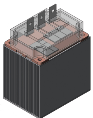 Figure 1: This is an insulated gate bipolar transistor module that is mounted to a parallelplate aluminum heat sink. |
As integrated circuits (ICs) are continually being introduced that offer more cores and higher clock speeds, they are being asked to dissipate increasing amounts of power. Add microprocessors running at multiples of the intended clock speed to gain a performance edge and products being developed for a wide range of markets, and the thermal management challenge increases further as systems have different cooling requirements. As a result, doubts have arisen as to whether the most powerful among them can be cooled with air. The primary alternative, liquid cooling, can handle higher heat loads, but is considerably more expensive and has higher maintenance challenges than cooling with air.
Engineers at Amulaire Thermal Technology of San Diego, CA, which custom designs and offers catalog heat dissipation products, recently evaluated alternate methods of cooling a 100-kilowatt (kW) insulated gate bipolar transistor (IGBT) module dissipating 2kW of heat.
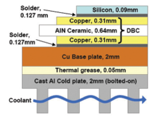 Figure 2: This diagram shows the thermal resistance stack from the diejunction to the heat sink surface. |
Cooling a 2kW IC
Amulaire set out to quantify the challenges and concerns by focusing on a 100kW IGBT power module dissipating 2kW of heat because it is commonly used in both converter and inverter circuits. IGBTs are primarily used for switching between static and dynamic states in cycles and in inverter circuits for both power supply and motor drive applications. The advent of 3D multilayered packaging of IGBT modules can help achieve better reliability, lower electrical noise, and reduced costs. However, this approach places electronic dies closer together, increasing heat flux and heat density.
In any of these applications, one power dissipation component is generated, which heats up the semiconductor and adds to the total power dissipation of the switch. The maximum junction temperature is typically 150 degrees C for these devices, but lower temperatures are desirable to improve reliability. Air-cooled heat sinks have been the conventional choice, but as some military and commercial applications have reached multimegawatt requirements, aluminum has given way to copper heat sinks, which were then replaced by liquid cooling due to the perceived limits of air cooled heat sinks.
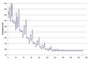 Figure 3: Heat sink thermal resistance decreases during optimizationprocess. |
At Amulaire, we used Flotherm computational fluid dynamics (CFD) software from Flomerics to optimize heat sink design for the IGBT under a number of different assumptions. The main reason we chose this software package is that it offers the ability to automatically optimize the design of a heat sink or any other aspect of thermal management. The user simply defines design goals in the form of a cost function and the range over which key design parameters can be varied. The software automatically creates and runs the required number of simulations to explore the entire design space in the most cost-effective way. Flotherm then generates a response surface showing the value of the design goals for all the combinations of variables that were run.
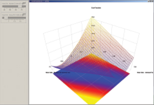 Figure 4: Response surface optimization enables engineers to visualizecomplete interaction of design parameters with design goal. |
Optimizing Heat Sink Design
Flow analysis and heat sink optimization was performed to define the limits of an IGBT heat sink-fan assembly. The power electronic circuit uses a direct-bonded copper technique using a power electronics module with an integral copper heat spreader. The module-heat spreader assembly is bolted to an aluminum heat sink using a thermal grease interface. A wrought aluminum (6061-T6) heat sink was used as the starting point for optimization. Forced convection through the ducted heat sink was provided by a fan curve representing a Comair Rotron model MT12B3 axial fan. This fan has a maximum airflow of 0.1415 cubic meters per second (cmps) (300 cfm) and a maximum static pressure of 206 Pa (0.811 in. of H2O). The sequential optimization solver was used to optimize the number of fins, fin thickness, and base thickness. Because the fan curve was used in the simulation, the flow rate, velocity, and pressure drop were affected by these design parameters.
Starting with 10 fins, a fin thickness of 0.40 mm, and a base thickness of 4.0 mm, the optimization process was allowed to adjust the variables within a +/- 30 percent range. If the optimum for the variables was at the minimum or maximum of the range, another 10 solver runs were used starting from the previous optimum. If the optimized value was not at the minimum or maximum, another 10 runs were performed within a range of +/- 10 percent. If the optimums did not change after a second run using the same starting point, 20 solver runs were initiated with a range of +/- 5 percent. If the optimum still did not change, the solution was considered to be complete.
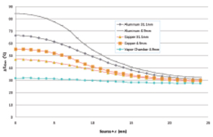 Figure 5: This chart shows a comparison of spreading resistance for varioustypes of heat sinks. |
Air Cooling Proves Sufficient
The optimization of the aluminum heat sink demonstrated the limitations of aluminum. The end result was a 54mm thick, 60cm x 60cm, aluminum heat sink having 127 fins, 1.21mm thick. Using the fan curve described previously, this results in an airflow of 0.08672 cmps (184 cfm), a pressure drop of 84.1 Pa (0.331 in. of H2O) and a surface area of 15.6m2. The overall heat transfer coefficient is about 1.501Wpm2 K, which results in a temperature rise of 85.4 degrees C and a heat sink thermal resistance of 0.0427 degrees CpW. Using the stipulated 50 degrees C ambient temperature and the thermal resistance from the junction to the heat sink, the junction temperature is about 184 degrees C, which is clearly unacceptable.
This simulation shows that regardless of size, an aluminum heat sink is unable to cool this chip because of the spreading resistance: The bigger you make an aluminum heat sink, the less efficient it becomes due to spreading resistance.
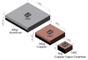 Figure 6: This shows the overall improvement from aluminum, then tocopper, and then to a vapor chamber heat sink. |
Copper offers substantially higher thermal conductivity (390 Wpm K) than aluminum (180 Wpm K), so its performance in this application is naturally higher. The optimization showed that a copper heat sink 40cm x 40cm x 10cm would meet the temperature requirements. The problem was its weight was too high for the vast majority of applications.
Recognizing that spreading resistance was the challenge to overcome in this application, Amulaire engineers tried a vapor chamber heat sink with copper fins. Vapor chambers are plate-shaped heat pipes that can be used as the base of the heat sink. They transfer heat more efficiently over a plane, minimizing spreading resistance of the heat source. Vapor chambers are also less expensive, less complex, and more reliable than liquid cooling systems. The optimization showed that by reducing spreading resistance and using the outer area of the heat sink more efficiently, the vapor chamber reduced the required size of the heat sink to 20cm x 20cm x 10cm. This, in turn, reduced the weight of the heat sink to 9kg or about 20 pounds, which was deemed acceptable for most applications and is about the same as a liquid cooling system.
Thermal simulation and automatic optimization techniques were the keys in our ability to demonstrate that many of the cooling issues in high-powered chips with aluminum heat sinks might be due to the material’s high spreading resistance. They also showed that while copper provides a substantial improvement, its weight might be an obstacle in demanding applications. Vapor chambers provide much lower spreading resistance and, therefore, can more efficiently use the full area of the heat sink.
More Info:
Flotherm
Flomerics Inc.
Marlborough,MA
flomerics.com
Ralph Remsburg is the chief engineer at Amulaire Thermal Technology. Send an e-mail about this article to [email protected].
Subscribe to our FREE magazine, FREE email newsletters or both!
Latest News
About the Author
DE’s editors contribute news and new product announcements to Digital Engineering.
Press releases may be sent to them via [email protected].


