Helping design and engineering professionals discover, evaluate and specify technologies and processes that shorten the design cycle and enable success.

May 2026 Special Focus: Artificial Intelligence in Design and Simulation
In this Special Focus Issue, learn about the latest developments in the integration of artificial intelligence into engineering workflows.

April 2026 Special Focus Issue: Generative Design
In this Special Focus Issue, Digital Engineering takes a look at how generative design solutions can be used across different types of design problems and with a variety of manufacturing approaches to accelerate design space exploration, and…
In February, a guest editorial in the Web-based newsletter upFronteZine News (Numbers 416 and 417) predicted a "3D format war" based onseveral factors: the adoption of Right Hemisphere's Deep View by Adobe,Autodesk's reported desire to make its DWF into the standard forinteractive 3D visualization, and the rather large number of suchformats now available.
Despite such dark predictions, the state of the art in interactive 3Dvisualization appears to be diverse, and to offer opportunities for thedifferent viewing formats available—depending on specific applications.Certainly, the vendors seem to be pleased with their currentopportunities.
"The differences in viewing technologies aren't really very dramatic,"explains Michael Lynch, CEO of Right Hemisphere. "They can all domeasurement, sectioning, markup, and related jobs. The issue isn't thetechnology, but rather the pipeline through which it reaches users."
Saying that visualization is a cornerstone of PLM—a viewpoint it's veryhard to argue with, especially in the areas of collaboration, BOMmodels, and archived designs—Lynch points out that many applicationsexist because 80 percent of mechanical engineering today is done in 3D."Our objective was to create an open, scalable system that isn't justCAD neutral. Most of the available tools are CAD-neutral, and mostfocus on authoring tools and format. Right Hemisphere believes the keyfor us is the back-end system."
| |
|
|
|
|
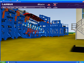
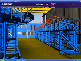
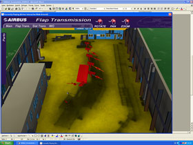
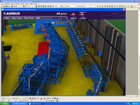
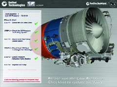
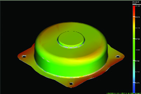
RightHemisphere technology was used to create interactive visualizations ofthe Airbus A380 High Lift Test Rig, a device used to mechanicallystress testand certify the advanced A380 wing design. Test rig MCAD data was converted,reduced, animated, made interactive, and exported. Images courtesy of FTI Engineering Network GmbH and Right Hemipshpere. | |
By back-end Lynch means "an open graphics server that works with anygraphic data, and to which users can add their own applications."Specifically, he says that Right Hemisphere offers a back-end serversystem that connects to "enterprise systems such as PDM (product datamanagement) and PLM (product lifecycle management) to read and outputgraphic data."
Although Right Hemisphere primarily focuses on direct sales to verylarge companies and does not normally OEM its technology, the companymade an exception in the case of Adobe. "The market for 3Dvisualizations is not only engineering. Adobe is a publishing companythat offers an intersection of technologies—manufacturing, engineering,technical documentation, marketing, training, RFQ (request for quote)development, support services, repair-on-site. In terms of universalviewing, Adobe is already there," says Lynch. "Up to 80% of likelyapplications are now served by Adobe. I think the ubiquity story is abigger one than the technology and features."
Technology for Wide Applicability: UGS
UGS' JT was the first lightweight visualization format. Introduced in1996, JT proved that MCAD model sharing was possible, without dealingwith huge MCAD files. Today, it offers "all the data in a CAD file,without the authoring tool," says Stu Johnson, product manager,Teamcenter Visualization.
Johnson says that Adobe is important at the publishing end of thevisualization spectrum, "but JT and UGS go far beyond that. Forexample, General Motors updates multiple terabytes of data everyday—and JT functions as a shadow of the whole authoring area for them."
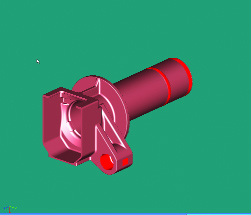
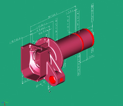
In addition to lightweight visualization, JT offers a highly accurateb-rep version of the geometry primarily for engineering purposes. Italso contains the Parasolid modeling kernel, so that users of NX, SolidEdge, and other Parasolid-based MCAD programs can be certain of nodeviation from the actual geometry. Its soon-to-be-released productmanufacturing (PMI) version will make tool path generation much easierand faster (see Figures 1A-1C, below).
"Users don't care about proprietary technology," Johnson says. "Theywant a product to do a job. They can build an ideal solution with JTbecause of its ability to store multiple levels of detail. The b-repsand PMI are stored in the model, but aren't downloaded into RAM untilneeded. The format can also stream data, so that users can start usingvisualization and manipulating the view while it downloads—and thedownload can stop when RAM runs out, without crashing the machine."
Johnson says that the JT file format is currently being used for suchdownstream applications as digital mockups for engineering andmanufacturing, design in context, paperless shop floors, technicalpublications, immersive concept visualization, marketing and salescollateral, ergonomics, tolerance analysis and simulation, and qualityassurance.
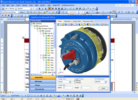
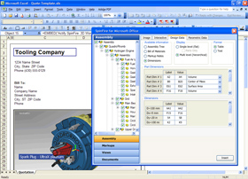
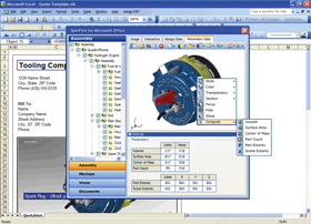
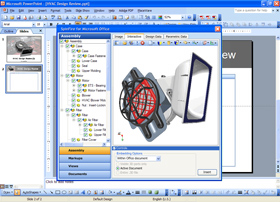
| SpinFire Put to Work This collection of screenshots shows how you can use Actify's SpinFireto create a variety of new 3D-enabled Microsoft Office documents. |
Electronic Folders improve Response: Actify
Actify wants users to see its .3D (say dot-3-D) workspace as a way togive them access to MCAD so they can leverage design data internallyand with suppliers, and work with PLM as a viewer.
"Think of .3D as a data container meant for exchanging data among usersof CAD, Microsoft Office, JPEG files—and a variety of other tools forinformation exchange," says Randy Ochs, president and CEO of Actify Inc.
"Companies want to produce better parts faster and cheaper, and thusneed to involve the supply chain early. SpinFire has reduced time tomarket for users by offering easy access to both 2D and 3D CAD data,together with fast communication," he adds.
What manufacturing companies really need, Ochs explains, is anelectronic folder for design, specifications, and documents forcommunication and collaboration.
Actify recently announced a new step in that direction with a productcalled SpinFire for Microsoft Office 2005—a tool that embeds .3D visualizationsinside Excel, PowerPoint, Word, and Outlook. The interactive 3Dvisualizations can be viewed and manipulated by people who have accessto either SpinFire Professional or the free SpinFire viewer (see"SpinFire Put to Work," above).
SpinFire for Microsoft Office aims to provide greater access and visibility ofdesign data to more people in both internal departments and the supplychain. "We see the value of SpinFire and SpinFire for Microsoft Office in beingable to share high end design without access to CAD," Ochs says. "Itanswers the need for useful data that can be used for collaboration,assembly data, procurement, manufacturing, QA, and fieldservice—resulting in productivity improvement."
Figure 1A, above, left: JT is a highly flexible fileformat that can include any or all of the following: Precisesurface geometry, multiple levels of detail for the tessellation, attributes, and PMI. | Figure 1B, above, right: UGS will soon releasePMI— product and manufacturing information—which will provide theinformation needed to manufacture a part without the need for a 2Ddrawing. |
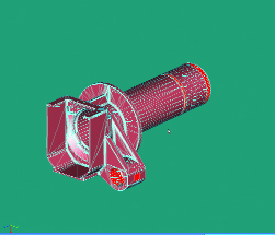
Figure 1C, above, left: Tessellation: JT parts are tessellated withtriangles to significantly increase graphic performance over the nativeMCAD part. JT files can also include the underlying surfaceinformation for precision operations or for re-tessellating asrequired. | |
Unlike the polygon-based (tessellated) motifs used by all the otherformats—excluding JT's b-rep version—Lattice 3D's XVL "resurfaces thewhole model inside and out to create a NURBS-based model," says JeffDrust, vice president of Business Development. "We use Gregory patches,which are good at handling curves. This is a math model thattessellates during viewing, and which avoids the problems ofvisualizing curves in polygon-based models when you zoom in close."
NURBS-based models are also more compressed than polygon-basedvisualizations, Drust points out. "If a user wants to increaseresolution, he can re-tessellate as part of the viewing process, ratherthan having to go back to the CAD model to create a new visualization.The size of the file doesn't change when you regenerate—and the modelis 98 percent compressed." However, if a particular applicationrequires a very detailed view, that can enlarge the size of the XVLfile somewhat.
Company Information | Drust explains that having NURBS-based visualization files helps userscreate more flexible animations. "Most animations are based on video,and are very large files that show a set of different frames asphotographed—so that it's not possible to change the viewpoint fromwhich they're viewed without doing a new video," he says. XVL, on theother hand, saves the data regarding which part moves, and where itmoves—in a very small file. "Users can move each part around duringanimation, so they can see anything from any and all viewpoints. Andthe user sets the degree of accuracy while viewing either stillvisualizations or animations," he adds.XVL incorporates clash detection and makes it possible to combinemodels made of parts that originated in different MCAD systems. Currentapplications include design review, comparison of as-designed andas-built parts for quality control, parts lists, technical documents,training, manufacturing, assembly, and packaging design. Lattice 3DEmbed also enables XVL files to be embedded in Microsoft Office andother documents—including PDF files (see Figure 2, above).Dassault Systemes was so impressed by Lattice's approach that it OEMsthe technology as the basis of its 3DXML, and CoCreate has also chosen XVL as a viewer for its Designer Modeling. A Rich FieldJudging from these four formats, it does not seem likely or necessaryto settle upon a single standard 3D visualization format. Part 2 willlook at more offerings—including DWF from Autodesk and solutions fromCimmetry—in the rich and growing field of interactive 3D visualization. |
Contributing Editor Louise Elliott is a freelance writer based inCalifornia. Offer Louise your feedback on this article through[email protected]. | |

DE's editors contribute news and new product announcements to Digital Engineering. Press releases may be sent to them via [email protected].
Follow DEJoin over 90,000 engineering professionals who get fresh engineering news as soon as it is published.


About Us · Contact Us · Editorial Team · Advertising · Privacy Policy · Subscriber Services · © 2026 Digital Engineering 24/7 · Peerless Media