

March 1, 2006
By Al Dean
Inventor 11 reaches maturity with sophisticated shapes, dynamic simulation, and large assembly performance.
Autodesk, Inc. has expanded Inventor’s capabilities over the last few updates, but with Inventor 11 the company is now also taking advantage of the fruits of some recent Autodesk acquisitions. After witnessing a hands-on demonstration of the modeling tool’s eleventh major release, this is the year Inventor passes another milestone. With that in mind, DE took a look at the major areas of improvement in version 11 to see how they will enhance your working processes.
Release 11 offers tools that should ease the challenge many designers face with regard to large assembly performance. These tools should make life easier, especially when it comes to the ability to create Assembly Configurations. While previous releases allowed you to define variants of a part using a table-driven input method, the same has now been applied to assemblies, letting you vary dimensions and parameters, and replace components-all of which is supported in data management and downstream Inventor applications such as drafting and documentation.
Another assembly-related feature is Level of Detail representations, which let you store a range of your assembly model’s variations that have specific components suppressed. This allows you to load the exact data you want whether it is work packaging, sub-systems, or loading the product’s structure. Another great feature is the capacity meter, which shows what system resources you have left on your machine, so you can see when you’re about to hit the performance ceiling in terms of processor loading and RAM allocation.
Advanced Shape Description
In these days of hyper-competitive markets, everyone-not just consumer product designers-has their eye on product aesthetics. Inventor has always taken a beating for the lack of its complex geometry creation tools: i.e., Surfacing. R11 has changed this in dramatic fashion.
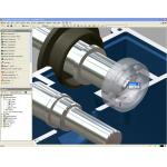
º º The new Advanced Shape Description tools allow you to create much more aesthetically pleasing forms, using either surface modeling techniques or the enhanced Filleting tools, such as the face to face fillets shown here.

The 3D Sketch tools have been reworked to allow greater control and easier manipulation, which is particularly critical when creating the often complex networks of curves required in the surface-style design process. And there’s been a lot of work done on the Loft and Sweep functions, both of which are critical when you need to create complex shapes. Generally speaking, these operations now have control over both tangency and continuity, but there are also new options, such as the ability to loft to a point (ideal for closing out complex lofted forms), you can sweep a profile, normal to a surface, and loft using a centerline.
Alongside these core tool offerings, other new tools create n-sided patches, ideal for patching in complex shapes (with the G1 and G2 controls) and repairing imported data. Of course, you can’t have advanced shape design tools without some new Filleting tools. For R11, this means G2 continuity is also added to edge-Filleting operations, as well as new commands that allow full rounding (which wraps three adjacent faces with a single fillet) and face-to-face Fillet forms.;)
¹ ¹The Sculpt tool is used here to take a set of untrimmed, individual surfaces and to create a valid solid in a single feature.
One feature that’s worth looking at in some detail is the new Sculpt tool. As a starting point, this tool lets you take a group of untrimmed surfaces (either native or imported) and very quickly trim and stitch them together to create a solid form. Sounds good, right? It goes further. You can use the same operation to use specific surfaces to trim away or add material to an existing geometric lump, again, using a single or group of surfaces. It’s quite difficult to explain the potential for this tool, but it’s going to be useful in a lot of areas such as when dealing with imported data and when dealing with complex surface intersections.
Functional Design
Autodesk introduced Functional Design in the last two releases, where the user defines function and form using standard design and engineering language as opposed to the often cryptic geometry and dimension-based workflow. The idea is that you define your products with functional requirements, such as performance, size, weight, power consumption, cost, and durability rather than a list of parametric modeling features.
 |
º º Here you can see the tools within Inventor that allow you to drag and drop standardized components from the Content Center and have them adapt to the mating component - using standard sizes and variants.
While R10 saw the preliminary introduction of the tools from Mechsoft, R11 sees better integration of these tools into core Inventor functions, and consolidating the often disparate dialogs and methods of accessing those operations. All of the Component and Mechanical Generators (for the likes of bolted/screwed connections, shafts, hubs, and bearings, as well as the intelligent definition and calculation of joints, plates, bearings, and such), as well as the Engineer’s Handbook are handled within a single dialog.
|
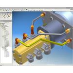
¹ ¹ Functional Design related updates are widespread, but in the Tube and Pipe environment, it means that you can define piping runs that can better handle design updates and modifications.
Programmers have worked to make R11’s assembly creation process more dynamic, a good example of which is the reworked method of placing bolted connections. You first choose a standard bolt from the Content Center, which is located at your cursor. As you move the bolt to a reference point, its size is automatically adjusted to suit, and you get a shaded preview. What is more impressive, though, is that you can drag the bolt to a correct length-based on standard lengths-by grabbing and stretching the threaded end.
Functional Design is also influencing other areas of the system. Pipe runs in the Tube and Pipe module are now based on their route and the relationship between the various entities, rather than dimensions. And the new Steel Frame Generator allows the user to mix up the geometry (such as solid geometry and wireframe or skeletal) modeling methods to define the form of a steel structure.
Simulation
One of the real highlights of R11 is the introduction of dynamic simulation, a result of the Solid Dynamics acquisition that took place in the third quarter of 2005. It was a surprise to see the integration work already under way for R11 and while not complete, it is a good start.
º º The new Dynamic Simulation tools allow you to take Inventor assemblies and carry out kinematic simulation work to find out exactly how a product operates. Here, you can see the joint force definition dialog.
;)
;)
;)
;)
The simulation tools currently available in R11 allow the user to carry out dynamic analyses based on real-world constraints and build in all the factors that influence motion. The system is supplied with a library of motion joints with friction, damping, and stiffness. These are either defined manually or built semi-automatically based on assembly mates, although it’s often the case that the mates you’d use to define a static assembly model aren’t necessarily those you’d use for motion simulation. You can control driving loads and moments using time-based force functions, and the system includes all of the 3D motion visualization, graphing, and report tools you’d expect. You can also take the time-step with maximum stress or force transference and have the associated forces moved across to the part Stress Analysis tools.
;)
¹ ¹ Once the Dynamic simulation work has been done, you can select a time-step, such as where maximum forces are created on specific, critical parts, then transfer that information for use in the Stress analysis tools also built into Inventor.
Reaching a Milestone
Inventor 11 might just be a milestone for Autodesk, where the promises and potential of a system finally start to bear fruit. The introduction of the advanced shape description and assemblies handling tools in R11 mean that users can get more out of the core capabilities within the system. The work done to consolidate and improve the various functional design tools means that more users can take advantage of its benefits as barriers to adoption, such as the former distinct lack of a cohesive workflow, have been removed. This version’s introduction of the motion simulation tools into Inventor Professional as well as tools that allow bidirectional working with AutoCAD Electrical means those on subscription are getting a good amount of new functionality for their extra investment. In addition, Inventor Professional now includes updates to Tube and Pipe, and Cable and Harness tools. It’s clear that Inventor is finally reaching the level of maturity that its position in the market place demands.
Al Dean is Technology Editor of the UK’s leading product development and manufacturing journal, MCAD and is Editor of Prototype, for the rapid prototyping and direct manufacturing industry, both available by clicking here. Send your comments about this article through e-mail by clicking here. Please reference “Inventor 11, April 2006” in your message.
Subscribe to our FREE magazine, FREE email newsletters or both!
About the Author
DE’s editors contribute news and new product announcements to Digital Engineering.
Press releases may be sent to them via [email protected].


