Measuring Right for All Your Needs, Part 1
Enterprise Metrology closes the loop with MCAD.


Latest News
October 1, 2005
By Steve Logee
Enterprise Metrology closes the loop with MCAD.
Part 1 of 2: An integrated evaluation of the data stream and what it’s good for.—DE Editors
Dimensional measurement systems are the yardsticks we use to gauge the fidelity of our parts and assembled products against the designer’s intent. When there’s a discrepancy between measurement and model, we correct it either by changing the manufacturing process that is causing the problem or reconciling the MCAD model to reflect ad hoc changes made to improve upon the original design. At least that’s how it’s supposed to work.
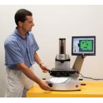 |
| This Tesa Visio manual system can be programmed and controlled in a virtual environment based on an imported MCAD model. |
• Generating reports based on the data and analyses. Once the software has measured a part and analyzed the results, it has to generate some sort of report. What the report looks like depends on its audience, and audiences vary. Typically, users output their information in a range of predefined layouts. These include both tabular and graphical formats and allow for some mixing and matching of the two. For custom reports, the system must give users total control over the formatting of their reports, allowing them to include whatever elements best suit their individual purposes. The software should provide SPC reporting where needed, including reports on special types of parts like gears and blades.
• Publishing the information. The final function an EM system must accomplish is getting the information where it needs to go as quickly as possible. And it should do this using a wide range of formats and media. The information has to serve all sorts of purposes from automatically adjusting machine tool offsets to transmitting reports for
authorized users throughout an organization. MCAD Tools for EM
Existing tools for the publishing of metrology data work well enough, but they tend to be overly reliant on proprietary technology and human intervention. This is changing quickly. The next generation of EM publishing tools will take full advantage of Internet and intranet technologies. With them, producers and consumers of metrology information will be working in a standard environment (i.e., Internet Explorer). These publication tools will make it easier for producers to control the distribution of their reports, and authorized users will be able to easily access them.
In today’s world, the best manufacturing processes start in the design room. For EM systems to be truly effective, they have to do the same. CAD-resident EM tools expedite the flow of data, measurement programs, and information throughout the enterprise.
The idea of communicating dimensional requirements and information between MCAD systems and measurement devices, usually CMMs, is not new. Starting in the 1980s, the Dimensional Measurement Interchange Standard (DMIS) established just such a protocol. DMIS made it possible to develop part programs offline on a MCAD system and send them to a CMM for execution.
Under this scenario, it’s often the MCAD operator’s job to develop and debug part programs. The big advantage of this approach is that it eliminates the need to send inspection plans (blueprints marked up with GD&T information) to CMM programmers. In some organizations, this approach works very well, but in others, it fails. When it fails, it’s usually because the technicians charged with developing the programs don’t have the appropriate mix of MCAD skills and understanding of the limitations and capabilities of the measurement machines that will be checking the parts.
New ApproachesRecent advances in computer, networking, and software technologies have made another approach possible. It is now practical to send MCAD files directly to measurement machines. Here, metrology programmers, using automated tools, interact with their models in developing and debugging large portions of their inspection programs. During program execution, the results are evaluated directly against the MCAD definition of the geometry. These tools save enormous amounts of time and, because the nominal values come directly from MCAD, eliminate a major source of errors. Unfortunately, the programmers still have to get their tolerance information from marked-up blueprints and enter it into their measurement routines. This is a slow process and prone to problems in both data entry and interpretation.
;)
This may look like a CMM program but it’s not. The programmer used PC-DMIS NC from Wilcox Associates to write an NC probing routine offline. The machinist can use the routine as stand-alone application or incorporate it into the NC machining program. Data collected by the routine may be used to simplify NC setups, make tooling offsets, perform in-process metrology operations, and used for SPC analyses.
At Wilcox Associates we’ve developed an approach that eliminates this last bottleneck by making the entire process paperless. PC-DMIS Inspection Planner Suite leverages the GD&T capabilities of MCAD systems like SolidWorks or Unigraphics by giving designers a set of tools for embedding design intent into their models, and it leverages the capabilities of modern measurement software to read in MCAD models by adding routines that automatically interpret these enhanced models. The benefits of paperless inspection plans embedded in MCAD are numerous. Part two of this article will explore these benefits in the next issue of DE.
Steve Logee is the director of business development for Wilcox Associates. Send comments about this article via e-mail by clicking here. Please reference “Metrology, November 2005” in your message.
Subscribe to our FREE magazine, FREE email newsletters or both!
Latest News
About the Author
DE’s editors contribute news and new product announcements to Digital Engineering.
Press releases may be sent to them via [email protected].


