

Latest News
April 1, 2006
By Andrew Johnson
Dynamic-mesh CFD method offers new ways to model a hummingbird’s flight, and that’s just for starters.
Simulating complex fluid-structure interactions, such as airflow around a flapping wing, has been a long-standing challenge for the high-performance computing (HPC) research community. Those of us studying nature in the hopes of mimicking complex animal behaviors (as in hovering birds and insects) in mechanical systems have found this issue particularly vexing, until now.
Theoretically, one way to simulate flow around dynamic geometries is to use dynamic, adaptive meshes. But creating dynamic meshes with conventional techniques is extremely difficult and, for some complex simulations, impossible.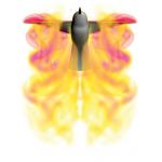
› › Shown is a 3D volume-rendered image of vorticity magnitude at an instant during the hummingbird’s mid-forward stroke. As can be seen, the downward flow created by the wing’s motion is fairly strong and has a complicated structure. The average lift generated by the wings in this simulation is around 4.5 grams, and real hummingbirds of this size weigh on the order of 4 grams.
At the Army High-Performance Computing Research Center (AHPCRC) in Minneapolis, we wondered whether we might be able to solve this problem by merging automatic mesh generation (AMG) technology with our parallel flow solvers.
Getting Dynamic Meshes Off the GroundAs anyone who has tried to tackle CFD problems involving complex fluid-structure interactions has discovered, these problems can be very difficult and complicated. Simulations can quickly go bad as mesh elements stretch, twist, and tangle. Such applications have always been challenging, and there has been no easy, general-purpose, or reliable solution.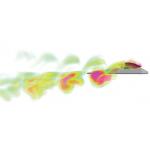
‹ ‹ This is a 3D volume-rendered image of stream-wise vorticity of airflow past a flapping-wing micro-unmanned aerial vehicle (UAV). The wings are modeled as a bending electro-active polymer that bends up-and-down based on electrical current fed to the wings. As can be seen in the rendering, a complex vortex structure is created in the flow at each beating cycle. This micro-UAV model and wing motion is generating positive lift and thrust throughout this simulation of cruising flight.
Historically, many researchers relied on “remeshing” whenever the mesh went bad, but that strategy is very time-consuming, complicated, and cumbersome, and generally produces less than accurate results. Instead, we wanted to integrate AMG methods directly into our parallel flow solvers, so that the mesh could dynamically adapt to changing conditions and geometries during the simulation. However, actually implementing this coupling is no small task.
In the first place, such a strategy should run in parallel and must overcome the inherent limitations of programming models such as message-passing interfaces (MPI). (To create a functional dynamic mesh, HPC system processors modeling different sections of the mesh must communicate with each other, which traditionally has meant using MPI.) While MPI is fine for many applications, it has too many limitations and adds too much latency to be effective for dynamic mesh simulations. In addition, writing the code to parallelize AMG with MPI would be incredibly convoluted, complicated, and time-consuming. However, over the last few years, new parallel programming tools have emerged that can eliminate the need for MPI and open the door to much more efficient and practical parallel implementations of dynamic mesh techniques.
In early 2005, we began working with the new parallel programming language Unified Parallel C (UPC) with the goal of building new types of codes that would be difficult or impossible to implement using MPI. We quickly recognized that UPC would allow us to create a new type of CFD code that supported much more complex simulations, including dynamic mesh methods.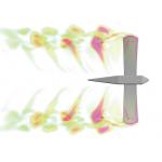
› › This 3D image of stream-wise vorticity of airflow is at the same time-step as that in the previous picture above, but views the micro-UAV from the top. The same complex vortex structure can be clearly seen created in the flow at each beating cycle. Even though such systems can’t be effectively built today, we can begin to study these applications by modeling them on the compute to see how the wing motion is generating positive lift and thrust.
We began using UPC to build a new CFD code, called XFlow, that could parallelize AMG methods in an efficient and general-purpose way. We were also fortunate to have a Cray X1E System available that provided the fast network and efficient memory framework to support a parallel global address space model at the hardware level, and allow us to fully exploit the advantages of UPC. One of the first major problems we attacked with the new code was a detailed simulation of a hovering hummingbird.
As in any conventional approach, we began by using AMG software to create a 3D unstructured mesh of the space around the hummingbird and its wings. The initial mesh contained roughly 4.5 million tetrahedral elements. We then fed the mesh into our parallel flow solver, which partitions and distributes the mesh among the Cray X1E System’s processors to solve the governing equations for the airflow around the hummingbird and its flapping wings.
However, unlike conventional CFD codes, XFlow combines our AMG methods and routines with the flow solver. Throughout the simulation, these routines periodically change the mesh to account for geometric changes and preserve the quality and refinement of the mesh. The resulting dynamic mesh changes the element connectivity and resolution throughout the simulation. These changes are made during “dynamic mesh update stages,” which happen after each time-step is computed (assuming any changes are required). Unlike remeshing, the changes at each time step are very subtle. Only a small fraction of the mesh is changed from one time-step to the next.
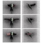
‹ ‹ Shown here is the unstructured tetrahedral element mesh at a cross-section through the domain at three time instances during the simulation. The 3D mesh in this simulation started with around 4.5 million elements and ended with around 7.5 million elements. Throughout the simulation, the mesh was growing in size. As can be seen above, the dynamic mesh CFD methods of XFlow does an excellent job at preserving the quality and refinement of the mesh during these rather drastic motions of the hummingbird’s wings.
The end result was an extremely detailed simulation of the fluid flow around a hovering hummingbird and its flapping wings, as well as the lift and drag forces the wings produce. Initial comparisons with experimental data demonstrate that the technique provides a very realistic simulation solution. We demonstrated the model at the SC05 Supercomputing Conference in November 2005.
Onward and UpwardWe’ve now used this method to simulate a hovering hummingbird with unprecedented detail and accuracy, as well as performing several other simulations. We believe the technique provides a natural, general-purpose, and user-friendly strategy that could one day serve as a valuable tool in a variety of scientific and engineering applications with wide range and potential.
Along the lines of applying what we learn from nature to mechanical systems, we developed a simulation of a micro-unmanned aerial vehicle (UAV) that uses flapping wings. Even though such systems can’t be effectively built today, we can begin to study these applications by modeling them on the computer. More recently, we’ve begun modeling simple rotorcraft, fluid-particle flow, and blood flow through an artificial heart.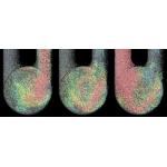
;)
› › This is a simulation result of blood-flow through a pumping artificial heart at three time instances as generated by the XFlow code. These results show the applicability of dynamic mesh CFD (and XFlow) for complex biomedical applications. The flow results visualized here use a special particle-tracing technique to track and animate mass-less particles that are carried with the fluid. The colors of the particles correspond to the velocity of the fluid (and particle) at each location.
This dynamic mesh CFD method has proven to be general enough to be applied to a variety of fields. In the future, we can envision the strategy applied to applications such as complex engine, turbine, and pump design; additional biological and biomedical applications; and simulations of free surface flows, among others.
Researchers working on complex applications with moving components speak about the ways they would like to model fluid-structure interactions in an ideal world. But they inevitably say they were forced to find other solutions, because such methods were difficult, impractical, or impossible. With dynamic-mesh CFD, we hope we can offer a step toward realizing that ideal world, and provide a useful general-purpose tool for researchers and application developers.
Dr. Andrew A. Johnson is a senior scientist with the Army High-Performance Computing Research Center at Network Computing Services Inc. in Minneapolis, Minnesota. Dr. Johnson performs research and development activities in the areas of computational fluid dynamics, high-performance and parallel computing, automatic mesh generation, geometric modeling, and large-scale scientific visualization. Dr. Johnson holds a Ph.D. in aerospace engineering from the University of Minnesota. You can send an e-mail regarding this article by clicking here. Please reference “Perfect Flight, May 2006” in your message.
Army High-Performance Computing Research Center
Minneapolis, MN
Cray, Inc.
Seattle, WA
SC06 Supercomputing Conference—2006
Subscribe to our FREE magazine, FREE email newsletters or both!
Latest News
About the Author
DE’s editors contribute news and new product announcements to Digital Engineering.
Press releases may be sent to them via [email protected].


