
October 1, 2006
By Al Dean
Analysis has become an integral part of SolidWorks software—at the base level with COSMOSXpress, which is included in every seat, through to the more recent introduction of COSMOSWorks Designer into SolidWorks Office Premium. The latter is aimed at the majority of users, and includes tools for static analysis of both parts and assemblies (stress, strain, and displacement). COSMOSWorks 2007 introduces some new tools as well as enhanced existing tools for the setup of analysis studies.
For example, it’s now possible to define cyclic symmetry within a study where features repeat in a circular pattern. Also, in terms of analysis-study setup, h-adaptive technology is now available for meshing assemblies (it was previously available for parts only). This technology lets you refine meshes automatically using built-in intelligence, rather than guesswork.
|
|
| COSMOSWorks 2007 |

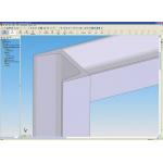
> > Figure 1: COSMOSWorks 2007 can now analyze weldments created in SolidWorks using beam elements, which are much more efficient for such forms.
On the subject of building in intelligence, COSMOSWorks 2006 introduced the Analysis Library, which enabled a more experienced user to define a set of predefined analysis processes. These could then be safely deployed to non-experienced members of a team. Now, with COSMOSWorks 2007, you can assign upper and lower limits for values within that library, allowing the expert to generate templates that have specified limits, thus removing another potential cause of user error.
Elsewhere there’s been a lot of work done to use a number of tricks used by analysis experts. These tricks have been formalized into features to make the system more intelligent and usable by designers. First, you can now include outsourced parts without having to mesh and analyze the whole form. These can be represented using Mass Elements and are based on the mass properties and moment of inertia information from the SolidWorks model. Second, you can now take a weldments model and analyze the structural components using beam elements (see Figure 1, above). The system automatically derives the beam cross-section from SolidWorks geometry, creates the joint conditions, and reads the loads and supports applied to the weldments—reducing rework to a minimum.
|
|
| COSMOSWorks 2007 |
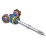
< < Figure 2: The new Bearing Connector lets you to replace a physical bearing with a virtual component to duplicate the behavior of a bearing. This connector provides the ability to input local stiffness as well as free rotations.
Along the lines of reducing effort, is the use of Connectors, which has increased with each recent release. These allow you to define commonly found conditions, such as the interface between components, joining methods, and component behaviors, using a black-box type feature rather than manually defining the often complex interaction or action.
COSMOSWorks 2007 offers a new Bearing Connector that lets you quickly define a bearing using factors such as stiffness and rotation freedom, and let the system create the FEA form required (see Figure 2, above). There’s also been work done on the pre-existing connectors. The Spring Connector now allows simulation of just tension or compression, and can also define between cylindrical faces or two points/vertices (see Figure 3, below). The Bolt Connector no longer requires users to split the faces around a bolt to define its contact area. Finally, for those looking at nonlinear analysis, the existing Pin Connector is now supported by the nonlinear analysis tools available in the Advanced Professional products. This, too, reduces rework as you move studies from linear-static to the nonlinear realm.
|
|
| COSMOSWorks 2007 |
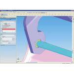
> > Figure 3: The existing COSMOSWorks Spring Connector has been enhanced to simulate tension-only and compression-only springs. In addition, springs can now be defined between cylindrical faces or two points or vertices.
Interpreting Results
Of course, while the setup of your analysis study is key to accuracy, the real work is involved in the interpretation of the results that you receive back from the system. This release provides a wide range of updates to the visualization and inspection tools available in all of the COSMOSWorks products.
One interesting new feature is the ability to predefine Sensors that provide feedback results at specific locations within the model. These can then be used to retrieve results such as stress and displacement on a repeatable basis. The results at Sensors can be saved per plot and displayed while printing or creating reports.
The uses for these are pretty open. For example, they can be used to validate analysis results against physical test data. Elsewhere, in terms of results visualization, you can now manipulate clipping planes using drag handles and can display values of stress above yield strength in a distinctive color to indicate areas of potential failure.
Finally, you can now use the Animator/Camera introduced into the core SolidWorks environment with the COSMOSWorks plotting tools.
Final Progress Report
In addition to the core updates I’ve covered here, those within the SolidWorks community should already know that COSMOSMotion is now a part of the SolidWorks Office Premium bundle. SolidWorks has recently taken charge of the development of the Adams-based motion simulation system from MSC.Software and work should offer improved integration and interactivity improve between the systems and COSMOSWorks. But what of COSMOSWorks 2007?
First, it’s clear that SolidWorks is looking to make the most of the integration of core product design tools with simulation and analysis. This release shows how that is being played out, where the system is both gaining functionality that is more advanced as well as taking advantage of the benefits of modern 3D modeling.
|
|
| COSMOSWorks 2007 |
< < COSMOSWorks 2007 lets you analyze assemblies of thick, thin components, weldments, and purchased parts using a combination of solid mesh for thick bodies, shells for thin bodies, beams for weldments, and equivalent mass for purchased parts.
The Connector technology is particularly interesting as it removes much of the magic from the FEA process and allows engineers and designers to define their problem studies using real-world language and terminology. Also, the Analysis Library tools allow an expert to define how a particular recurring problem is solved and package that workflow into an easily distributable form that everyone involved in the design process can then reuse.
With the accelerated integration between SolidWorks and COSMOSWorks, SolidWorks Corp. has made it economically viable for organizations to adopt production-ready analysis and simulation as part of its workflow. That should always equate to better quality products and that’s what it’s all about.
Al Dean is Technology Editor of the UK’s leading product development and manufacturing journal, MCAD and is Editor of Prototype, for the rapid prototyping and direct manufacturing industry, both available by clicking here. Send your comments about this article through e-mail by clicking here. Please reference “COSMOSWorks 2007, November 2006” in your message.
Advanced Offerings of COSMOSWorks 2007
Alongside the COSMOSWorks Designer tools bundled with SolidWorks Office Premium, the COSMOS product family also includes a number of upgrades to expand your capabilities. For example, the COSMOSWorks Advanced Professional product brings more advanced, higher-end tools where you need to conduct nonlinear analysis on plastics, rubbers, polymers, and foam or where large displacements are occurring. New for COSMOSWorks 2007 is the ability to stop the solver for a nonlinear analysis at any time, and then re-start from the last solved step. Elsewhere, friction is now supported for nonlinear contact analysis, and you can now define Follower Loads.
Another key part of the COSMOS product family is COSMOSFloWorks, which provides the CFD (computational fluid dynamics) analysis component within the SolidWorks product offering. This release provides greater integration with SolidWorks, seeing most of the dialogs ported over to the PropertyManager pane, which is a core part of the SolidWorks workflow. The new Animator feature in FloWorks allows you to create high-quality animations involving flow-analysis results. These can be output as AVI files to show flow trajectory and particle tracing.
On the function front, COSMOSFloWorks 2007 concentrates on three areas. First, the new Thin Wall Technology—which SolidWorks says is unique to the product—automatically detects thin-walled segments in your model and captures the thin walls within one cell. This eliminates the need to apply mesh control to capture thin geometry. This technology will also accurately capture the boundary layer near the walls.
Second, you can now model the Cavitation phenomena, commonly found in the design of piping, valve systems, and the like. It occurs when the pressure in a system drops below the vapor pressure of the liquid, resulting in bubble formation and very high acceleration of those bubbles, which can lead to material erosion and failure. FloWorks can now predict areas in the model where cavitation will occur and report where pressure and density will be found, allowing the designer to avoid such occurrences.
Finally, FloWorks can calculate the relative humidity in every location of your model — particularly useful for climate control applications like clean room processes, saunas—and users can now input the value of relative humidity (as a percentage) to every opening in the model. —AD
COSMOSWorks 2007 At a Glance
Geometry Types
• Assembly analysis
• Parts analysis
• Shells, thin parts, sheet metal parts
Analysis Types
• Drop test
• Fatigue
• Frequency and buckling
• Heat transfer—steady state and transient
• Motion simulation
Environments (Loads/Restraints)
• Body loads: gravity and centrifugal
• Directional and non-uniform pressure and force
• Directional and prescribed restraints
• Fixed restraints on edges and vertices
• Fixed restraints on faces
• Force on edges and vertices
• Special loads: torque, remote, bearing
• Stress and displacement
• Temperature, convection, radiation, heat power
• Temperature-dependent materials
• Thermal stress
• Uniform pressure and force on faces
Visualization
• Dynamic section, iso plots
• Factor of safety calculation and plot
• Principal stress, directional stress, strain plots
• Resonant frequencies, mode shape plots
• Result probing, listings
• Stress plot, deformation, and displacement plot
• Temperature, heat flux plots
Other Features
• Animation and save as AVI
• Export to other FEA systems
• HTML reports and report customizations
• Publish eDrawings of analysis results
• Save as bitmap, JPEG, VRML, or XGL
Note: This partial list of features covers COSMOSWorks 2007 Professional.
Contact Information
COSMOSWorks 2007, Designer, Professional, Advance Professional
SolidWorks Corp.
Santa Monica, CA
Subscribe to our FREE magazine, FREE email newsletters or both!
About the Author
DE’s editors contribute news and new product announcements to Digital Engineering.
Press releases may be sent to them via [email protected].


