Reverse Engineering: Magic, Mystique, and Myth
Truth be told, reverse engineering will not walk your dog, but it can open doors to new applications and products.


Latest News
August 1, 2005
By Todd Grimm
When you need 3D MCAD data of a physical object for redesign, replication, analysis, or inspection, reverse engineering is an excellent tool. By enabling you to capture hundreds of thousands of points in a few seconds, scanning technology is ideal for feature-loaded, complex, or organic shapes.
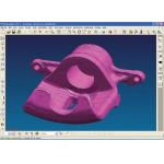 |
| Imported into Unigraphics, the scan data yields a dumb solid that is used to create solid or surfaced model files with feature and parametric recognition. Image courtesy of Berding 3D Scanning, Milford, Ohio. Click on image to enlarge. |
Object scanning has little in common with its 2D document scanning counterpart. Although fast, it is not a push-button operation that delivers solid models ready for redesign and feature manipulation. As in the MCAD design world, the scanning systems and software provide the tools, but the quality of the output is dependent on the skills of the operator, time invested, and the geometric features of the part.
A prevalent misconception—that is, one of the myths swirling around reverse engineering—is that the scanner output provides data in a format that can be directly used in a solid-modeling system. The reality is that the scanner’s point-cloud data must be processed and that the imported data yields a “dumb” solid. So, design and documentation in the native MCAD system will demand that the imported 3D model be used to create a feature-driven, parametric solid model.
The good news is that many projects do not need a parametric or feature-based MCAD solid model. The application of stereolithography—STL—files (polygonal mesh models) has extended well beyond rapid prototyping. STL files can also be used for machining, duplication, CAE, inspection, and many other applications. When the end product is an STL file, the process is simple, efficient, and fast.
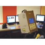 |
| Figure 1: Reverse engineering systems consist of a scanner (foreground) and software for processing point cloud data. Image courtesy of Berding 3D Scanning, Milford, Ohio. |
And your investment doesn’t stop there. A typical part will take between two and 24 hours to process into NURBS surfaces, and additional time will be needed to make a workable solid model. The good news, for those who do not have the budget or the resources, is that there are many qualified service providers eager to tackle any project.
Point Cloud GenerationReverse engineering starts with the scanning of a physical object. But unlike 2D document scanning, it is not a single-step, push-button operation. With the exception of X-ray CT (computed tomography) systems, MRI (magnetic resonance imaging), and the destructive process offered by CGI, all scanners require line of sight to the features that will be captured. This means that each part will require multiple scans in multiple part orientations. Ten to 20 scans are common for even the most basic parts. For complicated parts, that number can swell to more than 100.
Line of sight also means that the scanners will only capture external surfaces. For hidden, internal geometry, CT scanners, MRI scanners, or the CGI process are your only options.
For each scan, the output will be a point cloud of data that documents X, Y, and Z coordinates and, for some systems, an additional value indicating color or intensity. Typically, each scan will contain somewhere between 50,000 and 2,000,000 individual points. When using a scanner attachment on a CMM (coordinate measuring machine) or articulated arm, a single scan can have millions of points.
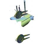 |
| Figure 2: Noise, which includes unwanted scan data features (top) is removed (bottom) with automated and manual software tools. Image courtesy of Berding 3D Scanning, Milford, Ohio. |
Here’s a rundown of the major steps of processing scanned data.
Clean Data—Raw scan data will contain noise (i.e., stray data points) and unwanted features—for example, the table on which the part was scanned (see Figure 2). The first cleaning step is automated. Using mathematical algorithms, the software detects some of the outliers and removes them from the point cloud. Next, any remaining noise and features are manually selected and deleted from the point cloud.
Align Data—Aligning (also called registration) the individual scans combines both automated and manual tools. If an indexed, rotary table is used to scan a part, a preregistration may be done automatically. The same is true if the object is marked with targets. These automated functions are often performed by software supplied with the scanning hardware. But it may also be automatically aligned within the scan data processing software.
When distinct features or targets are available, the automated process will perform the preregistration well. However, even with a successful preregistration, the scan data must be repositioned with manual alignment tools.
Merge Data—Merging data creates a unified data set from all of the individual, aligned scans. The output is a raw polygonal mesh that requires further processing and refinement. Unlike the previous steps, this process is a push button, fully automated procedure. 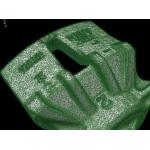
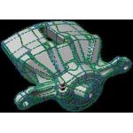
Figure 3: A brake system component illustrating the polygonal mesh that is used to feed applications and to create NURBS surfaces. Image courtesy of Berding 3D Scanning, Milford, Ohio. Click on image to enlarge.
Refine Polygonal Mesh—For anyone who has output STL files, this process will be familiar. After specifying a few parameters—for example, a chord height deviation—the mesh is automatically created (see Figure 3). However, as with STL output from a solid-modeling system, repair is often needed.
The repair operations will produce a smooth, watertight polygonal mesh. Repair operations include filling holes, sharpening edges, and smoothing surfaces. Holes in the STL model result from hidden (or shadowed) geometry or sparse data points in a localized area. Small gaps are automatically filled while large holes require manual definition of “bridges” that span the gap.
Somewhat surprising to many, sharp edges cannot be reproduced by the scanners. So, sharp edges and corners must be created. This is done by extending adjoining surfaces and trimming them to their intersection. In some software programs, there are tools to create sharp edges in a semi-automated fashion.
Surface smoothing can be completed with automated algorithms that reposition data points based on the average of surrounding points. Unlike an MCAD-generated STL file, the need for smoothing is not always a function of the facets of the polygonal data. For example, laser scanners can produce an “orange peel” effect.
 |
| Figure 4: The brake component from Figure 3 with curves and surface patches. Image supplied by Berding 3D Scanning, Milford, Ohio. |
NURBS Surfacing—In those applications where 3D MCAD data is required, the time and talents of the technician have a major impact on the output quality. Building good NURBS surfaces that are true to the original part can be time-consuming and tedious. Although the software can automate NURBS surface generation, it is up to the technician to manipulate the data to the quality needed. Before surfacing begins, it is important to define the intended purpose for the data. The application and required surface quality directly impact the time and effort for the process. So, for anyone requesting reverse engineered data, it is critical that the applications be specified and communicated to the scanning technician.
Reverse engineering software programs offer different methods of generating NURBS surfaces. These include draping (think shrink wrap); automatic edge/feature detection and patch generation; and manual definition of curves that define individual patches. If using automated surface generation, expect to intervene with manual modification of surface patches. While the auto-generation tools do a fair job, the results are not ideal for most applications (see Figure 4).
The surfacing tools, their techniques, and their output vary from one software package to the next. So, when you are in the market to purchase software, surface generation is a key area to evaluate.
Export/Import—Following the creation of the NURBS surface data, the file is exported as a 3D, trimmed surface IGES or STEP file. This data is then directly imported into the MCAD modeling system of your choice.
Building MCAD DataAlthough the file is now directly importable, the process is not finished for users who need a CATIA, Pro/Engineer, SolidWorks, Unigraphics, or other solid model. The imported data file has no intelligence. It is a dumb solid that does not recognize features like cones, spheres, and cubes (see the top figure in this article).
Often the reverse-engineered file will be imported as a collection of independent surfaces that must be stitched to create a surfaced or solid model. Also, there is no parametric definition. What this means is that modeling, even for basic changes like alteration of a fillet, requires the creation of a new MCAD solid from the imported reverse-engineered data.
While the imported solid can be cut, scaled, offset, or used for Boolean subtractions, all other operations require the creation of new solid entities. The imported data becomes the reference set from which to build the new solid model.
Seeking to minimize the effort in recreating an MCAD solid, reverse engineering software companies are pursuing methodologies, some of which are just now becoming available, that allow features to be defined from the polygonal data. The result is a B-Rep model that eliminates some of the work needed to create a usable solid model.
Used Right, Nothing Beats ItThe reverse engineering process may appear to be complicated, and the steps can be time-consuming, but for the right applications, nothing can beat reverse engineering. In a world of intricate parts and organic shapes, imagine creating 3D digital data with a CMM. It is unthinkable that a few hundred points could accurately define freeform and feature-rich shapes. If it were attempted, imagine how long it would take.
Also, remember that not all applications require a native MCAD data set. The STL file shortcuts much of the time-consuming process, and it is viable input for applications like 3D visualization, dimensional inspection, finite element modeling, mold flow analysis, machining, and, of course, rapid prototyping.
Reverse engineering does not replace CMMs, nor is it a panacea for all data gathering challenges. It complements them in a way that opens the door to new applications, new possibilities and a broader slice of the physical world. Reverse engineering can work magic for design, manufacturing, and quality control.
Todd Grimm is president of T. A. Grimm & Associates in Edgewood, Kentucky (tagrimm.com), an independent consulting firm that focuses on rapid prototyping and reverse engineering. Todd is chairman of the Society of Manufacturing Engineers’ 3D Data Capture/Reverse Engineering technology group. Send your comments about this article by clicking here. Please reference August 2005 RE article.
Editors’s Note: For hyperlinks to reverse engineering service bureaus as well as to vendors of reverse engineering hardware systems and software, click here.
Berding 3D Scanning
Milford, OH
CATIA
Dassault Systemes
Woodland Hills, CA
CGI
Eden Prairie, MN
Pro/Engineer
PTC
Needham, MA
SolidWorks
SolidWorks Corp.
Concord, MA
Unigraphics
UGS Corp.
Plano, TX
OK, How Long Does It Take?
To create NURBS surfaces, a golf club head takes 6 to 7 hours and an airfoil (one foot tall) takes 20 to 28 hours. Here’s the breakdown.—TAG
Club Head Airfoil Tennis Shoe
Scanning: < hr 1-2 hr 1-2 hr
Alignment: 0.75 - 1.75 hr 3-4 hr 1.5 hr
Clean, Repair: 2 hr 4-6 hr 3 hr
NURBS: 3 hr 12-16 hr -16 hr
And What You’d Say It Costs?A freestanding laser or white-light scanning system, with software, will cost between $47,000 and $100,000.
Scanner: $10,000 to $300,000
Software: $20,000 to $30,000
For scanning services, a typical part will cost $500 to $2,500, based on an hourly rate of $100.—TAG
Subscribe to our FREE magazine, FREE email newsletters or both!
Latest News
About the Author
DE’s editors contribute news and new product announcements to Digital Engineering.
Press releases may be sent to them via [email protected].


