Simulating for an Edge
Computer simulation helps America's Cup competitors maximize yacht performance.


Latest News
May 25, 2007
By Alan Smythe
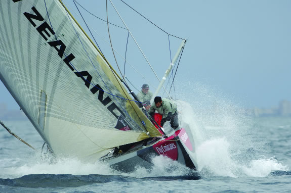
The teams of the 32nd America’s Cup are composed of the best sailors, designers, sailmakers, nautical engineers, and boat builders in the world. The top teams will expend more than 150,000 man-hours to optimize the design of their boats for the most famous and most prestigious regatta in the sport of sailing. All of the leading teams are using computer simulation to determine power generated by sails, drag produced by boat hulls and keels, and air resistance on deck. Four of the top teams, defending champs Alinghi, Emirates Team New Zealand, BMW ORACLE Racing, and Shosholoza are using computational fluid dynamics (CFD) software from ANSYS, Inc. to predict the effects that design alternatives down to the smallest details have on yacht performance.
 Emirates Team New Zealand confirming the results of their analysis work. |
As the oldest active trophy in international sport, the Cup was first awarded to the schooner America in 1851 after a race around England’s Isle of Wight. Since then it has been known as The America’s Cup and was last awarded in 2003 to Swiss challenger Alinghi, which will defend its claim to the Cup beginning later this month off the coast of Valencia, Spain.
Since 1992, the regatta has been open to the International America’s Cup Class sloop, a monohull with an average length of about 75 feet. Because of exacting rules, the competitor’ boats are very similar and the two most critical aspects of the yachts’ performance are the aerodynamics of the sails and the hydrodynamics of the hull and its appendages. The art of yacht design is to generate lift from the sails in a manner similar to an aircraft wing. The keel generates lift in the opposite direction to prevent the boat from moving sideways and can be much smaller than the sails because it operates in a liquid about 800 times denser than air. Improving yacht performance, then, is basically a question of maximizing lift and minimizing drag —small changes in geometry often make the difference between a competitor and an also-ran.
BMW ORACLE Racing
For the 2003 race, BMW ORACLE Racing used a public domain CFD code to simulate the performance of its yacht but found that they could not ultimately distinguish between small design changes. For the 2007 race, the team has switched to ANSYS CFX from ANSYS, Inc. It allowed designers to run models with 10 to 15 million elements on large clusters of computers to resolve the performance impact of the smallest design changes. BMW ORACLE Racing designers simulated the performance of large numbers of different sail shapes and trims in order to understand how they perform under a variety of conditions. They evaluated the aerodynamic effects of the deck, such as the shape of edges and corners and where the winches are placed. They also looked at the shape of underwater components such as the ballast bulb.
 |  |
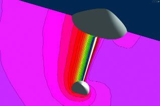
| Constant total pressure surfaces (like the one here in orange) are a good way of visualizing vortices, seeing how they diffuse and where they go. You can clearly see the vortex escaping off the bulb. | The defending champs, Alinghi, used ANSYS CFX to simulate the wind flowing over the deck and cockpit of the boat. Notice the vortex in the bow where the wind wraps around on the deck. |
“Our new simulation methods make it possible to model the most complex problems down to the finest details in a day or two,” said Ian Burns, design team coordinator for BMW ORACLE racing. “We can now determine the effect of the smallest changes, such as the shape of the deck or small hardware components on the mast. Some of these changes can have a significant impact on performance and are helping us make significant performance improvements. We have analyzed and improved nearly every detail of the boat with ANSYS CFX.”
Team Shosholoza
South Africa’s first America’s Cup entrant, Team Shosholoza, is one of the smaller teams competing and has only one boat. As a result, it can’t rely on running two boats against each other to evaluate design changes, making computer simulation critical. It has built a 42-node cluster that puts it at or near the top in terms of computing capabilities among the smaller teams. The team used CAD software to develop a parametric model of the boat, and then uses ANSYS ICEM CFD Hexa, which quickly generates a series of models by varying a key design variable over a defined range. Shosholoza then solves the models with ANSYS CFX and designers feed the predictions for force and drag into a velocity-prediction program.
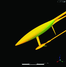
 BMW Oracle used ANSYS CFX to simulate flow around the keel-bulb to evaluate. |
“To date, the area where we have made the greatest improvements is in the shape of the sails,” said Christos Pashias, Fluid Dynamicist for Shosholoza. “We are trying to get as much power out of the sails as possible because the winds in Valencia are so light.”
By automatically generating sail models, the team was able to have quick turnarounds to study more shapes. Initial improvements of between 5 and 10 percent in driving force typically increases the speed of the boat by about 0.5 to 1.0 percent.
“We have tested boats with the new designs and discovered that they actually do provide the performance improvements that ANSYS CFX predicts,” said Pashias. “Since we made those initial big gains we have made many other improvements that have provided smaller gains, typically in the area of 1 percent, which is what most teams are typically after.”
Shosholoza also uses FLUENT CFD software to better understand the flow of water around a yacht. FLUENT software’s ranking of candidate hull shapes has agreed well with experimental results.
 Velocity magnitude contours around the keel and bulb of the BMW Oracle yacht in a plane perpendicular to the boat’s longitudinal axis. |
Emirates Team New Zealand
Emirates Team New Zealand has been focusing on improving the ballast bulb at the bottom of the boat. Weighing about 19,000 kilograms, this torpedo shaped lead component makes up nearly 80 percent of the mass of the yacht and provides the stability to balance a very large sail area. Choosing a bulb shape with a lower center of gravity increases the righting moment of the yacht and enables the sail to provide a larger driving force. On the other hand, moving to a lower drag force wastes less of the available driving force and increases the speed of the yacht. In preparing for the 2003 race, Emirates Team New Zealand designers were able to substantially lower the center of gravity without any increase in drag.
With these major improvements under their belt, the goal for 2007 was to make more subtle changes, such as optimizing the bulb design for the expected conditions off Valencia.“We developed a genetic algorithm that works by defining the geometry of the bulb with control points whose coordinates and weighting are considered to be genes,” said Nick Holroyd, designer for Emirates Team New Zealand. “Then the population was seeded with a range of candidates and mutations were introduced into each generation to adequately spread the population across the design space.”
After simulating with ANSYS CFX using the laminar-to-turbulent transition model to provide a drag value, engineers factored in the stability contribution of the shape and developed a family of new bulb shapes with better drag-to-stability trade-offs for the specific racing conditions expected at Valencia.
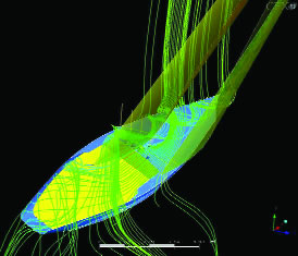
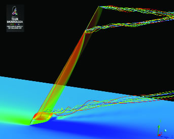 This screen shows an upwind aerodynamic simulation by Team Shosholoza. The tip vortices are clearly visible. Induced drag reduction is important for sails operating near their maximum lift. |
Alinghi
The defender of the Cup, Alinghi, uses ANSYS CFX to evaluate every portion of the boat including the sails, the underwater portion of the hull, as well as deck details. Alinghi designers spent more than a year evaluating CFD results, testing in wind tunnels, and researching scientific papers.
“We gained confidence in ANSYS CFX and calibrated its results,” said Jim Bungener, CFD engineer for Alinghi. “The main areas where we have made performance improvements have been in the winglets on the ballast bulbs and the downwind sails or spinnakers. We have also made smaller gains in other areas such as winch placements and pillar shapes. These improvements have significantly increased the speed of the boat.”
Bungener also used ANSYS Structural software to identify the composite laminar structures that will withstand the loads on the hull while minimizing weight.
Computer simulation will play a key role in this month’s Challenger series and the final Cup match. With all of the entrants now using CFD to optimize the performance of their boats, different design groups have all come to generally the same conclusions and made substantial performance improvements. As a result, the boats have come closer together in terms of performance and teams are shooting for finer and finer meshes and larger clusters of computers to evaluate the effects of smaller design changes. The America’s Cup is thus becoming a showcase, not only for the world’s fastest yachts, but also for its most powerful simulation tools.
Information:
ANSYS, Inc. Canonsburg, PA ansys.com
Alan Smythe is a freelancer specializing in water sports subjects. For this article, he combined that expertise with a love of math and physics dating back to his days in grade school. You can send e-mail about this article here.
Subscribe to our FREE magazine, FREE email newsletters or both!
Latest News
About the Author
DE’s editors contribute news and new product announcements to Digital Engineering.
Press releases may be sent to them via [email protected].


