

Latest News
January 1, 2012
By Scott Stanton and Sandeep Sovani
With concerns over air pollution and petroleum supplies, the use of hybrid electric vehicles (HEVs) and electric vehicles (EVs) has come to the forefront as alternatives to conventional gasoline and diesel engines. Governments worldwide are promoting HEV/EV research. The U.S. government has announced $2.4 billion in funding for new designs of battery packs, electric motors and other components, setting the goal of 1 million HEVs on the road by 2015. The U.S. Department of Energy predicts that by 2030, alternative vehicles will comprise 28% of the total U.S. light-duty cars and trucks—a 20% increase from 2005 (source: Annual Energy Outlook 2007 with Projections to 2030, report DOE/EIA).
To meet these increased demands for HEV/EV applications, competition is intense to develop improved and cost-effective electric powertrains. In meeting these demands, leading automotive companies with HEV/EV initiatives are focusing on development efforts driven by simulation, rather than prototype testing.
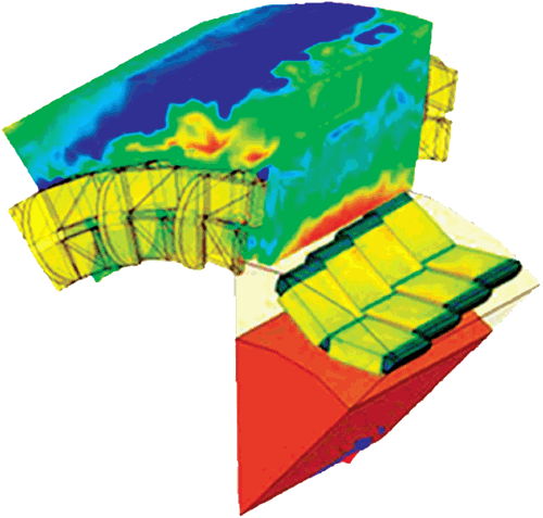
HEV battery pack cooling flow paths with temperature distribution on cells.
Numerous software solutions are available for the diverse types of analysis needed in such development work including mechanical, electrical, electromagnetic (EM), electrochemical, computational fluid dynamics (CFD) and thermal management applications.
Design Challenges
Today’s automotive engineers are challenged with designing new electric powertrain technologies almost entirely from scratch. Key components included in this task are electric battery packs, electric traction motors/generators and power electronics. The design of these HEV components involves complex physical problems—and an enormous amount of challenging system integration:
- Battery Packs: As engineers design batteries with large energy capacity and greater power output, they must consider the thermal, structural and EM influences on the battery pack—as well as the cells within. For example, batteries generate heat while charging and discharging. The temperature of all cells within the battery pack must be strictly maintained within a few temperature degrees of each other. Otherwise, harmful internal current loops can form within the pack that drastically shorten battery life. This necessitates a cooling system—whether by air or liquid—and sometimes creates a side challenge of minimizing noise close to the passenger cabin. Drivers of HEV/EVs expect an ultra-quiet driving experience, which is not compatible with a loud cooling system.
Engineers must also take into account the physical placement of an electric battery pack within the HEV, as well as any stresses the battery will experience under a range of driving conditions. The battery must be designed to safely withstand multiple variables such as external heating, over-charging, over-discharging, nail penetration, crush or external short. The same safety goals apply to crash scenarios, in which passengers must be protected from toxic acids released from the battery during such an event.
- Motor/Generator: For years, automakers invested relatively little time and money in electric machine (that is, the electric traction motor/generator) design because the internal combustion engine was so widely used. These conventional engines accomplished what they needed to: Consumer requirements were met; emissions regulations were not as stringent; and oil prices were not a concern.
Today, all that has changed, with a huge amount of interest in new motors—and a correspondingly huge pressure on companies to develop the most efficient, cost-effective electric design. Brainpower and investment dollars are flowing into this area, and the electric motor, just as with the electric battery pack, poses its own set of design challenges.
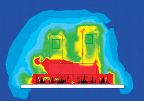
EMI/EMC of an Insulated gate bipolar transistor.
The motor/generator plays an essential role in the propulsion of the vehicle. It also recharges the battery via regenerative braking. HEV/EV traction motors are different from other motors because they must work reliably in a demanding physical environment. Motors must operate consistently under extreme hot and cold temperatures, severe vibrations, hard duty cycles and rough road conditions. In the HEV, an electric motor is also exposed to high temperatures produced under the hood by the engine. All of these variables must be addressed in motor design.
Customers also expect high fuel efficiency from HEV/EVs. Fuel efficiency, low emissions, safety and performance aspects of a vehicle drive consumer purchasing decisions and, therefore, directly affect market success. Because the electric motor design determines how much electrical energy provided by the battery is transformed into physical energy used to run the vehicle, designing a highly fuel-efficient motor is one of the most important challenges HEV/EV powertrain engineers face today.
- Power Electronics: The “heart and brain” of an electric powertrain system must precisely control the power transfer between the battery and the motor/generator, and also implement the logic to adjust the powertrain to various driving conditions and driver inputs. To operate at the highest efficiency under a variety of driving conditions, power supplied to the traction motor needs to be carefully controlled at a relatively high switching frequency. This is accomplished through devices such as insulated gate bipolar transistors (IGBTs), based on position, speed, temperature, etc., via feedback continuously received from sensors monitoring the motor.
Thermal management is a major concern with power electronics in HEVs. The entire power delivered by the electric powertrain to the wheels (as well as the power needed to recharge the battery) has to travel through the power electronics. Therefore, even the slightest power loss in the electronics creates a large amount of heat. The heat needs to be carefully managed and dissipated under a wide range of operating conditions, such as driving in a hot desert or in sub-zero winter conditions, to avoid heat damage to the power electronics and nearby components. Optimally, the electric losses in the electronics need to be accurately calculated, and heat dissipation paths need to be identified and designed to ensure effective cooling.
- Electromagnetic Interference and Compatibility (EMI/EMC): Because the power supplied to the motor needs to be controlled at relatively high switching frequencies, the EMI among the various electrical components becomes an important concern. If EMI is unaccounted for, it will destroy signals and prohibit the motor from operating. This requires a comprehensive study of the EM fields in and around the motor, bus bars and nearby components while these components are operating in an interconnected, coupled way.
From Theory to Practice
Multiphysics (MP) simulation software allows engineers to understand how a design will perform under various loading conditions before prototyping takes place. Not only can physical, real-life scenarios be modeled with accurate simulation, but the effects of and interactions between fluids, mechanics, thermal physics, electrochemistry and EM forces can be simulated and the design adjusted based on those models. In this way, designs can be generated faster—and systems can be optimized up front in the cycle, to avoid surprises and problems that might occur in the later stages of product development.
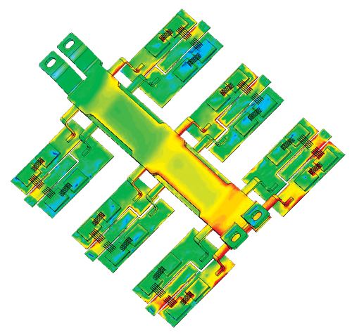
Insulated gate bipolar transistor temperature distribution.
Simulation tools for HEV/EV development span a wide range. They include CFD, EM, mechanical, thermal and electrical issues. These tools can be used in tackling the challenges of developing individual powertrain components—electric battery packs, electric traction motors/generators and power electronics—as well as the tremendous complexities when these subsystems are integrated into the complete vehicle powertrain.
- Battery Pack Simulation: For cylindrical cells, engineers typically employ an air-cooling strategy in which pack housings are shaped for optimal cooling, provided by a blower and guiding vanes to direct an adequate airflow. For rectangular cells, cooling generally is accomplished using liquid circulating through heat exchanger elements in contact with cells. A control algorithm is used to vary loads on different cells, based on temperatures and charger status.
In evaluating and optimizing the various thermal management configurations, parameterization and methods such as design of experiments (DOE) are used in combination with CFD solvers for analyzing the complex 3D cooling flows and conjugate (solid-to-fluid) heat transfer. For evaluating pack performance for long driving cycles, the linear time invariant (LTI) method is useful for efficiently performing such real-time simulations.
Engineers can apply electronics circuit simulation technology in evaluating the control algorithms for studying overcharging, high-current charging/discharging, external shorts or other electrical problems that could reduce battery life and risk battery explosion. The software can be used for studying such algorithms because of its ability to tightly integrate 3D physical models (CFD and mechanical) into the control circuit simulation.
For solving structural problems caused by incidents such as a crash or foreign body penetration of the battery pack, structural mechanics software can be leveraged to evaluate the structural integrity of the assembly to prevent toxic battery contents from escaping, or damage to cells that could cause thermal runaway and battery explosion. Such virtual prototyping is also useful in studying vibrations, as well as durability and fatigue life of the battery pack.
- Motor/Generator Simulation: In developing the motor/generator, the design team must focus considerable attention on the EM of this electric machine. From initial CAD drawings and related engineering specifications of the assembly, electronics design optimization software can be used to define the main elements of the motor/generator, including magnet materials, coil configurations, number of turns, air gaps and more. Parasitic extraction tools can be used to compute the machine’s electrical properties.
These outputs can be entered into EM field simulation software, which computes the torque profile of the machine—that is, how the torque ramps up over time for driving the vehicle in motor mode, as well as electrical resistance in stopping the vehicle in brake mode. Vehicle weight is brought into the analysis to determine acceleration and stopping time for various scenarios.
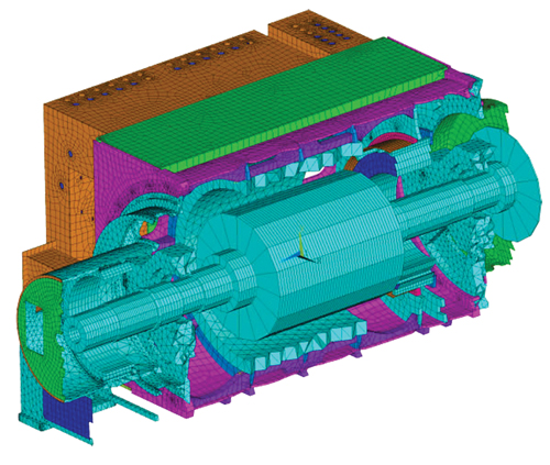
FEA mesh for shaft motor-generator. Image courtesy Kato Engineering.
The computed torque output may be used further in structural mechanics software for computing stresses, loads, deformations and vibrations of the physical parts of the powertrain, including the driveshaft and gearing. Vibration analysis is important because tractions can be a prominent source of noise in EVs, which are expected to be quiet by nature. CFD analysis may be used for studying thermal management issues, mapping energy losses, and determining heat distributions in the motor/generator assembly.
Throughout the EM and mechanical development processes, integrated MP software coordinates the actions and exchanges of data among the various tools in the many computations performed for different load scenarios, and in comparing various design alternatives. This MP co-simulation process is facilitated by the software all running on a single unified environment with a smooth flow of data among programs.
- Power Electronics Simulation: For thermal management of the HEV power electronics, engineers enter representations of IGBT characteristics (switching voltages, current waveforms, etc.), control algorithms (for turning the IGBT on and off) and the motor/generator into power electronics circuit simulation software for virtual analysis. From this data, the software determines how the levels of electrical current flowing through the entire system vary at given times for vehicle acceleration, cruising and braking.
Using electronic thermal current tools, engineers then specify the geometry of the major heat sources in the powertrain system (IGBTs and current-carrying parts of the motor/generator). Through parametric analysis, each heat source is applied individually at major points of interest in the system, with air circulation and conducted thermal energy taken into consideration. Software then processes this data and generates a thermal model, which engineers use to determine overall temperature profiles of each IGBT together with temperature-dependent performance variables, such as energy drained from the batteries to ensure that heat levels do not exceed specified limits to adversely affect IGBT performance.
From this temperature profile, engineers can utilize the thermal-structural analysis capabilities of FEA software to determine the resulting thermal stresses. Electronic design analysis tools can be applied to calculate EM forces acting on motor/generator components to determine deformations and mechanical stress distributions on the structure. Engineers can then modify the structure to eliminate stress concentrations and excessive deformation—or conversely, to lighten regions that may have been overdesigned with excess material.
- EMI/EMC Simulation: In HEV/EV development, switching speeds of IGBTs ranging from tens to hundreds of kHz—with turn-on rise times and turn-off fall times in the order of 50 nanoseconds to 100 nanoseconds—can cause two major EM problems:
- Conducted emissions (through current-carrying structures) can cause power integrity issues or set up reflected waves of energy that can potentially damage the inverter and the motor.
- Radiated EM fields (through air) can affect the rest of the vehicle’s many electronic systems.
Both types of interference problems must be considered. Engineers must design for EMI/EMC in vehicles.
To accurately characterize the behavior of a switching device such as an IGBT, engineers typically begin by using a parameterization wizard that takes into account performance curves and tabular data from vendor-supplied specification sheets. This process automatically extracts the required parameters to aid in creating a semiconductor circuit model of the IGBT.
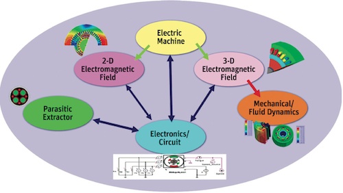
Hybrid electric vehicle and electric vehicle system simulation spans EM,
thermal, fluid and structural physics.
Next, the physical layout of the power inverter is imported from CAD geometry into parasitic extraction software, which then computes the frequency-dependent resistance, partial inductance and capacitance (RLC) along the conduction paths. The tool is used to create an equivalent circuit model for system simulation.
Results of these simulations can be used to examine radiated emissions, enabling engineers to calculate the field intensity at any given point in space to determine whether the inverter package is in compliance with federal and international standards.
System Integration
System integration is perhaps the largest challenge in electric powertrain development. Each component of the electric powertrain has distinct characteristics, attributes, strengths and other complexities that must be taken into account. The objective is to ensure that the entire electric powertrain performs at the highest overall efficiency under a wide variety of loads and operating conditions experienced in real-life driving scenarios. Because subsystems and components work together in a coherent, tightly coupled way, they cannot be developed entirely in isolation from one another. Rather, the performance of each subsystem must be carefully matched with those of all others.
Using Simulation to Prevent Battery Fires Editor’s note: With headlines trumpeting the potential for battery fires in GM’s Chevy Volts, the company has announced engineering changes to the structure around the battery pack as well as the addition of a sensor to observe battery coolant levels. Though no Volts have caught fire outside of testing by the National Highway Traffic Safety Administration, and GM has not issued a recall since the company says any such post-crash fire would not put drivers in danger. The changes can be requested by current Volt owners, who would like peace of mind. Because no manufacturer wants to see their product’s safety questioned, DE asked Sandeep Sovani, Manager of Global Automotive Strategy, at ANSYS, Inc., how simulation and testing might be used to avoid problems before production. Battery makers are concerned about the potential for fires in the lithium ion batteries used in the latest electric and hybrid vehicles. Two typical causes have been identified that can lead to a cascading reaction known as thermal runaway, which in turn can cause fires. The first is a short in a cell, which may be caused by a crash impact or by an impurity. The second is a blockage or other malfunction in the cooling system that cools the cells by running coolant through microchannels in the battery. There are hundreds of different variables involved in battery design that interact in complex ways that can affect the potential for thermal runaway as well as having an important effect on the efficiency of the battery. Cell and pack makers perform a considerable amount of testing during the development process to investigate the impact of these variables, but there is never enough time to come anywhere close to investigating the complete design space. Physical testing is also quite limited in its ability to evaluate battery performance under extreme conditions such as vehicle crashes. Simulation with tools such as computational fluid dynamics (CFD) and thermal analysis can fill the gap by enabling battery makers to evaluate a large combination of design variables under extreme conditions to determine their propensity to produce thermal runaway. For example, at the cell level engineers can simulate a short and determine how much heating will occur, how the electrochemistry in the regions of the cell surrounding the short will be affected, and whether phase change will create gases that may be trapped creating an explosive high pressure. Simulation can be run at the package level to ensure the cooling system is adequate to handle the heat generated by a short and prevent thermal runaway from occurring. With simulation, the cooling system can be extensively characterized over a wide range of scenarios so that the battery management system can be programmed to take effective countermeasures for any scenario. —Sandeep Sovani, Manager of Global Automotive Strategy, ANSYS, Inc. |
To successfully simulate such complexities in the HEV/EV powertrain, simulation solutions should be capable of multidimensional, multiphysical and multiscale simulation, providing the technology needed in addressing the many mechanical, fluid, electrical, electrochemical and EM issues of these complex powertrain systems.
The pace of HEV/EV development is incredibly fast, with original equipment manufacturers (OEMs) and suppliers alike having to meet challenging demands in a market with huge potential gains for cutting-edge companies. Instead, MP-based simulation-driven development can be used to balance the intricate, interdependent and often-conflicting mechanical, electrical, EM, fluidic and thermal management requirements.
Scott Stanton is technical director and Sandeep Sovani is manager of Global Automotive Strategy for Canonsburg, PA-based ANSYS Inc.
MORE INFO
References:
J.S. Hsu, C.W Ayers, C.L. Coomer, R.H. Wiles, S.L. Campbell, K.T. Michelhaugh, “Report on Toyota/Prius Motor Torque Capability, Torque Property, No-Load Back EMF, and Mechanical Losses,” Oak Ridge National Laboratory, Oak Ridge Institute for Science and Education, ORNL/TM-2004/185.
S. Stanton, D. Lin, Z. Tang, “Interior Permanent Magnet Machine Analysis Using Finite Element Based Equivalent Circuit Model,” IEEE Vehicle Power and Propulsion Conference 2009 proceedings, pages 291-294, ISBN 978-1-4244-2600-3.
Subscribe to our FREE magazine, FREE email newsletters or both!
Latest News
About the Author
DE’s editors contribute news and new product announcements to Digital Engineering.
Press releases may be sent to them via [email protected].


