

Latest News
September 1, 2004
By Joe Greco
The MCAD product that advanced the most in 2003 was Solid Edge; UGS released two powerful updates during that year, versions 14 and 15. Now it has just starting shipping its first upgrade in 2004. So let’s see if this release continues the improvements at the same pace that we saw last year and let’s study how Solid Edge’s key enhancements compare to its major competitors in the mid-range MCAD market.
Assembly UpdatesFor the last few years one of the philosophies at UGS has been to make assembly creation easier by using the idea of Systems Design. In version 16, several new enhancements address this issue, starting off with Adjustable Parts, which builds upon a Systems Design feature introduced in V15 called Adjustable Assemblies. An adjustable part is an item that may have a different shape, depending on where it is used, an example being a spring, as seen in Figure 1 (above, right). When such a part is made adjustable, as different versions of it are inserted, there is no need for new file names or part numbers. In past releases of Solid Edge there was no way to handle this, but V16 has a solution.
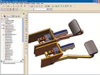 Figure 1: Solid Edge 16’s new Adjustable Parts enhancement allows a single part to have different sizes depending on where it is used, as seen in this spring. When a part is made adjustable, as different versions of the adjustable part are inserted into a design, there is no need for new file names or part numbers.
Assemblies frequently require numerous fasteners and Solid Edge 16 makes their handling easier and smarter thanks to a few new tools. The first is a new capability to automatically insert fasteners into their proper location based on the hole size. All the proper additional hardware such as nuts and washers are also placed. I did notice an oddity—possibly due to the late beta I was using—after two parts are placed and mated, if the fasteners are added and then the Undo command selected, not only are the fasteners undone, but so is the placement of the second part.
Another common trait of assemblies is that they are frequently symmetrical; however, some parts need to have right-hand and left-hand components, while others, like fasteners, can just be rotated to the other side. To solve this problem, Solid Edge has implemented a smart mirror function that allows users to determine which parts get mirrored and which get rotated. I found this feature very intelligent and easy to use, and it also allows specified parts to be omitted, as seen in Figure 2 (below, right).
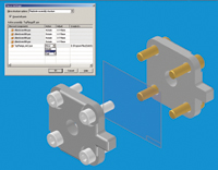 Figure 2 (right): Solid Edge 16 has an intelligent mirror tool that automatically figures out which parts should be rotated and which ones mirrored, all handled via a simple user interface. Rotated parts are created as instances in the same assembly, whereas mirrored parts generate a new file.
A type of Adjustable Parts has been in SolidWorks for a while. Autodesk’s Inventor 9 just added what it calls Flexible Assemblies, which allow components, such as pistons, to have different positions, but it is not at the level of Solid Edge or SolidWorks yet.
SolidWorks is the only Solid Edge competitor that has a similar tool to automatically insert fasteners. The two programs are alike in that they both work with standard holes as well as just ordinary cutouts; however, SolidWorks offers a lot more automation. For instance, in Solid Edge it is possible to populate all the holes on one face; SolidWorks can do that and also fill all an assembly’s holes in one shot. SolidWorks also automatically picks the supporting hardware, whereas Solid Edge users must choose them manually. Both rely on a library of components. However, Solid Edge’s is extra (unless you use the limited amount of fasteners supplied with the software), whereas SolidWorks’s components are included in its Toolbox.
Both SolidWorks and Inventor have the smart mirroring capabilities of Solid Edge, and all three work fairly similarly. The trio automatically figures out which parts should be mirrored and which ones only rotated, and all preserve the mating conditions, although with SolidWorks this is an option. It’s important to make sure what you are doing is correct, because none of the programs creates an actual assembly mirror feature that can be edited later on, and only Inventor allows an undo.
Another important aspect of Solid Edge 16 is its emphasis on tools to move users from 2D to 3D. Last summer UGS announced “Evolve to 3D,” a four-step approach for moving 2D users to 3D, and V16 introduces more tools to support this “Hybrid 2D/3D Design” philosophy. For instance, for users moving from AutoCAD, Solid Edge 16 now is able to emulate the Model Space and Paper Space methodology. This is accomplished by allowing users to build geometry in model space through the creation of view ports. It also uses techniques such as projection lines to help users construct new 2D views from existing ones.
Another important new addition to Solid Edge’s Hybrid 2D/3D Design is what they are calling Virtual Components (see Figure 3, below). This allows you to set up an assembly structure before committing to the actual components, sort of like the way you can set up a PowerPoint outline with only slide titles, before committing to the actual presentation information—the charts, text, movies, and so on. Once the assembly structure is determined, later both 2D and 3D components can be attached to the structure and then it is “published” to create the actual assembly. I played with the system a bit and found it worked well, except that there should be an option to associate the structure with the actual assembly. 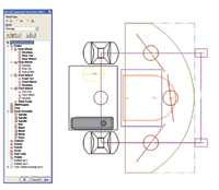
Figure 3: A very interesting concept in Solid Edge 16 is the idea of Virtual Components. On the left is the assembly structure that was created as a nongraphic way to conceptualize the assembly, and afterward, the actual components, both 2D and 3D, were added.
Solid Edge’s competitors all have different tools to help users move to 3D. SolidWorks has always had strong DWG import capabilities, and Inventor’s recent addition of layers and other 2D features has improved its 2D to 3D workflow. SolidWorks 2005 was just released and includes a full licensed copy of IntelliCAD to allow the editing of native DWG files. Neither SolidWorks nor Inventor uses the assembly structure of Solid Edge’s Virtual Components, but Inventor does have the ability to use 2D sketches—which may originate as DWG files—to drive the motion of 3D geometry.
Figure 4: Following the lead of SolidWorks, Solid Edge 16 now also includes the ability to create structural frames used to support items like the mechanical equipment seen here.
Upgrade Up to Par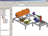
There is more to this release, including the ability to create frames (see Figure 4, at right), pipes, interoperability and Insight (PDM) enhancements, and a new rendering environment (Virtual Studio+; see sidebar, below, left)—one that brings Solid Edge up to par with its competitors.
Overall, this release isn’t quite up to the excellence of either version 14 or 15. However, it is still a very good and worthwhile upgrade for existing users. For users moving from 2D, Solid Edge offers some unique tools and concepts while keeping its modeling
Virtual Studio+: Photorealistic and Artistic Rendering Tool
Virtual Studio+ is a new companion photorealistic and artistic sketch-based rendering module for Solid Edge 16, which actually incorporates rendering technology from LightWork Design Ltd. (Sheffield, UK).Virtual Studio+ expands this functionality by providing more material libraries, backgrounds and foregrounds, textures, scenery, and light sources (ambient, point, spot, distant and sky). It supports LightWork’s sketch-based rendering for creating pencil-drawn artist renditions of MCAD geometry for early stage visualization and conceptual reviews.
Virtual Studio+ is a $495 add-on to Solid Edge.
Company Information
LightWork Design Ltd.
Sheffield, UK
UGS Corp. - Solid Edge
Huntsville, AL
Joe Greco is a Desktop Engineering contributing editor. You can send Joe your thoughts on this article via e-mail c/o Desktop Engineering Feedback.
Subscribe to our FREE magazine, FREE email newsletters or both!
Latest News
About the Author
DE’s editors contribute news and new product announcements to Digital Engineering.
Press releases may be sent to them via [email protected].


