Solid Edge 19 Muscles into the Limelight
SE's profile is on the rise since becoming the heart of the Velocity Series. Maybe now it'll finally get its due respect.


Latest News
August 1, 2006
By Al Dean
Now a cornerstone of the UGS’ Velocity series offering, Solid Edge’s profile within the market has gained a huge boost over the course of the past nine months since the last release. So, what does version 19 bring to the table for the mainstream modeling system?
The Transition from 2D
If you take a look at the typical Solid Edge user, they’re most likely to have come from a 2D background and, aside from those ME10 users out there, that is always going to mean AutoCAD. As with all the mainstream modeling tools, Solid Edge has always had tools that allow AutoCAD users to make the most of their data. With version 19, Solid Edge gives the transitioning user the ability to import AutoCAD DWG data and interact with it in a familiar manner. (See Bonus Image Gallery at the end of this review.)
|
|
| Solid Edge Version 19 |
› › In Solid Edge V19, PMI data can be stored with 3D models and assemblies.
When you open a DWG file in V19, you’re presented with a number of options that allow you to work with the data in a way that will be immediately familiar to any AutoCAD user. You can use display options (such as white text, black background), select layers for importing, line mapping, etc. What’s interesting is that once you import the data, it’s then held within the Solid Edge environment and you have to adhere to the system’s working practices.
Core Design Tools
Moving onto core product definition tools and updates to that core technology, the biggest news for V19 is the introduction of motion simulation and a completely redone Explode, Render, Animate toolset. This enables new gear-relationship types and motion drivers (motors) to be added to the assembly environment, which allows more efficient mechanism representation.
|
|
| Solid Edge Version 19 |

‹ ‹ Figure 1: V19’s new gear relationship functionality reduces system overhead and enables real-time solving of complex gear simulations.
Gears allow you to define a relationship of both circular (such as chain or belt driven, gears, cams, etc.) and linear (such as hydraulics/pneumatics) or indeed, a mix of both (such as a rack and pinion). Motors are used to put gears into motion, which allows you to define a rotary or linear input to drive a mechanism or system and use that to drive the motion simulation (see Figures 1 above and 2 below).
Following on from this, UGS reworked the Explode, Render, and Animate tools, creating a brand new environment. The new environment uses a keyframe/timeline-based approach to create animations. Everything within a dataset can be animated, from the parts and subassemblies, through lights, camera, and such.
|
|
| Solid Edge Version 19 |
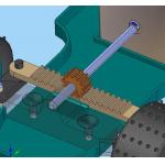
› › Figure 2: In Solid Edge 19 gear relationships provide a complete set of gear types (rotation to rotation, linear to rotation, and linear to linear). This example shows a rack and pinion steering mechanism.
The Animation environment includes a number of effects that can be integrated into the work quickly, such as fades. You can also take advantage of geometry-based path (using geometry) or keyframe interpolation (where the camera moves between user-defined positions) to quickly create product animations, whether that’s a simple turntable, a complex fly-through, or an assembly/disassembly.
All of this leads me rather nicely onto the next big update for Solid Edge 19: Exploded views. UGS has also overhauled these, particularly in terms of the intelligence the system can extract from the model (such as how it handles subassemblies) up through to the ease with which you can dive in and create the explosion sequence exactly how you want it.
Sheet-Metal Functionality
Right from the very first few releases, Solid Edge has always had an enviable reputation for sheet-metal modeling. But lately, the competition has perhaps started to catch up in terms of full process coverage—and in the world of software, if you stop, you quickly are overtaken. UGS has started again.
So with Version 19, you can now create deformation features for stiffening sheet-metal bends (that are handle-appropriate when flat patterning). You can create rolled and circular hems to remove sharp edges from sheet-metal components or use contour flanges that follow curved edges (see Figure 3, below).
|
|
| Solid Edge Version 19 |
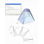
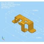
‹ ‹ Figure 3: Solid Edge V19 sheet-metal functionality has been enhanced with bend tables that indicate the bending sequence of a component as well as triangulation lines for transformation pieces such as square profiles to rounds or cones.
V19 also adds to the existing sheet-metal documentation tools to include bend tables that show bending sequences and accurate triangulation lines for transitional pieces (such as square profiles to cylinders). Finally, you can also now set up design checks that can warn if a flat pattern exceeds a specific blank size.
3D Annotation & PMI
UGS has always been ahead of curve when it comes to 3D annotation; both Unigraphics and I-deas have had the technology from a very formative stage. V19 sees that knowledge brought to bear in the company’s mainstream offering, allowing Solid Edge users to create 3D annotations (GD&T) directly within Solid Edge parts and assemblies (see opening image). This follows the conventions of how it’s been implemented in other systems, and allows you to use your existing annotation skills within a 3D environment.
Annotations are assigned using face and edge references as normal, but then assigned to specific viewing planes. The system handles their placement and alignment efficiently and intelligently to ensure that they can be read without ambiguity.
The primary reason for any organization seeking to take advantage of 3D annotation methods is the ability to accurately store PMI (production and manufacturing information) associated with a 3D CAD model within the same dataset, rather than within disparate drawings. In V19 that data can then be extracted and presented in a number of ways—in drawings, in the model in Solid Edge, or by using the collaboration tools Xpress Review or JT-based tools.
JT-Based Collaboration
If you take a look at the massive amount of discussion within the industry about 3D data format—such as with Adobe 3D PDF and Dassault 3Dxml—there’s one format that’s actually been made use of in a heavy production environment—and that’s UGS’ JT format. While the Packaged Collaboration Files have used JT under the hood since their introduction, this is the first release where Solid Edge has explicitly supported importing of the JT data format.
JT import for V19 allows you to import all the types of data that can be stored within the format—not only geometry, but 3D annotation as well. On the geometry front, JT is capable of storing both a full, accurate B-Rep surface model alongside a lightweight, tessellated representation.
When you export JT from your source system, you can select to include one, the other, or both. When importing data using File open or Insert Part Copy, Solid Edge opts for the full B-Rep data if available, but of course, you may just want the tessellated file for efficiency’s sake or to protect intellectual property.
Its Rightful Place
As said at the outset, Solid Edge is now a core part of the UGS’ Velocity Series offering. The Velocity Series combines Solid Edge with a low-implementation variant of TeamCenter, NASTRAN-based FEA, and, with this release cycle, the new NX CAM Express. We don’t have space to cover these in any great depth—nor have we had the time to look at the updates made to the Data Management offerings available outside of TeamCenter.
Still, taken as a stand-alone design system, Solid Edge has always delivered on the promises made by the mainstream modeling revolution. It’s easy to use for new users transitioning from 2D, and it can support that workflow until they’re ready to make the leap to 3D. Once working in the 3D world, Solid Edge is a well-developed system. Not only does Solid Edge enhance the design process through the well-established benefits of 3D, but it also takes advantage of the benefits of knowledge capture, data reuse, and collaboration that systems of this type offer.
Solid Edge has not sold as well as its competition, which, let’s be honest, is SolidWorks and Inventor. But with the fresh exposure and platform that the Velocity Series has given Solid Edge, it should take the position that it has always deserved within the market place—one of leadership based on the depth of its functionality.
Al Dean is Technology Editor of the UK’s leading product development and manufacturing journal, MCAD and is Editor of Prototype, for the rapid prototyping and direct manufacturing industry, both available by clicking here. Send your comments about this article through e-mail by clicking here. Please reference “Solid Edge 19, September 2006” in your message.
Solid Edge Version 19
UGS Corp.
Plano, TX
Bonus Image Gallery
|
|
| Solid Edge Version 19 |
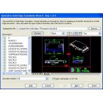
‹ ‹ UGS says that Solid Edge V19 provides true WYSIWYG (what you see is what you get) import of AutoCAD DXF/DWG files, including matching color schemes, fonts, styles and backgrounds.
|
|
| Solid Edge Version 19 |
› › Solid Edge V19 gives you the ability to animate models for creating dynamic documentation for such purposes as communicating design ideas, creating technical illustrations in maintenance and repair manuals, and providing assembly manufacturing instructions.
Editor’s Note: More images coming on August 29.
Subscribe to our FREE magazine, FREE email newsletters or both!
Latest News
About the Author
DE’s editors contribute news and new product announcements to Digital Engineering.
Press releases may be sent to them via [email protected].


