Helping design and engineering professionals discover, evaluate and specify technologies and processes that shorten the design cycle and enable success.

May 2026 Special Focus: Artificial Intelligence in Design and Simulation
In this Special Focus Issue, learn about the latest developments in the integration of artificial intelligence into engineering workflows.

Design & Simulation Software Guide 2025
In this Special Issue, Digital Engineering presents its second annual guide to design and simulation software vendors.
The need for analyzing an entire assembly or at least the essentialparts of a sub-assembly early in the design process is becomingincreasingly important.
When validating assembly 3D form and fit, real-world behavior understructural loads can be quite different from just the geometry anddimensional tolerances considered by CAD programs. Thereforecontact analysis is also a major factor when joining or matingcomponents with fasteners, such as rivets and bolts. Other thanexperimenting with an expensive and time-consuming physical prototype,finite element analysis is the only other reliable method fordiscovering whether or not such a mechanism will work.Adequate contact modeling is the crucial part of all assemblystructural design validation because their role in transferring loadsaffects the entire assembly. Additionally, contact tolerancesaffect manufacturing processes and reliability, as well as such costsas after-sale service and maintenance.
h-p Method for Speed and Accuracy
3G.author utilizes a proprietary adaptive FEA technology based on theh-p method. This adaptive FEA methodology automatically controlssimulation accuracy and speeds linear and nonlinear contact analysis.
The adaptive FEA technology, based on the h-pmethod, uses selective and simultaneous escalation of the polynomialorder of FEA approximation and local mesh refinement to reach fastconvergence of an approximated finite-element solution to a precisemathematical solution of the problem. This combines the strengthof both the p-method and h-method, where the p-method has high overallconvergence rates, and the h-method is excellent for local stress picksand concentrations. The assessments of numerical algorithmaccuracy are presented to the user in a simple to learn and understandway. 3G.author adaptive technology is applied to virtually everytype of analysis supported. Beginning with the initial blueprintthroughout multi-year development, the ability to run analysisadaptively and parametric associativity with a CAD model are twofundamental principles of the software architecture and design.
7. Adaptive analysis setup
An example of analysis accuracy for shrink-fit assembly testing isdemonstrated in pictures 7 and 8. The number of mesh refinementsand target accuracy is specified. When the solution is withinaccuracy targets, the adaptive FEA process generates a plottedconvergence curve for understanding the FEA approximationaccuracy. The process is straightforward and easy-to-use formainstream users. Without advanced FEA training reliablesimulation results can be achieved even for complex assembly validationcases.
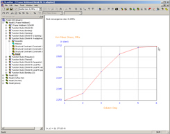
8. Adaptive analysis Convergence plot
3-D Solid and Shell Meshing
The default meshing functionality is fully automatedand transparent to the user, so mainstream user deals with virtually"meshless" process. The program begins by reading in a CAD modeland finishes with geometry related validation results in thepost-processing stage. The meshing algorithm automaticallydetects necessary mesh sizes based on the geometrical and otherpertinent information. The latter includes analysis type, contactinformation (contact entities undergo finer meshing by default),meshing type: 3-D or shell body mesh. The original mesh maybe changed after adaptive iterations with the option of previewing themesh at every stage of the process. The advanced user can use theentire meshing functionality with the ability to change global meshsettings and using local mesh control.
The assembly analysis is fully associative to any changes in CADmodels, if they are needed. 3G.author is fully associative withthe latest versions of the main popular three-dimensional CAD modelers,including: AutoDesk Inventor, Solid Edge, SolidWorks, Pro/ENGINEER, PTCWildfire. Data from CATIA can be read, as well as standardgeometry file formats like STEP, IGES, Parasolid and SAT. Withfull associativity, 3G.author provides access and graphical navigationto the entire feature-based and dimension-driven presentation of theCAD assembly. This makes it possible to drive importantdimensions within the package in order to validate a family ofassemblies or quickly estimate a design performance envelope byperforming what-if studies.
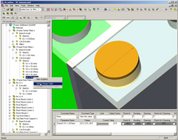
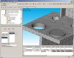
9. Mesh preview of the local controlled mesh
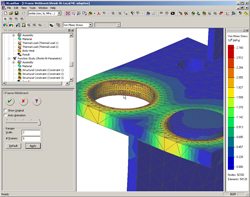
Picture 9 (above) demonstrates the mesh preview of a specialmesh control set for the shrink-fit area. The adaptive processrefines the mesh more in the area shown in Picture 10 (below). The usercan define the convergence criteria by defining convergence targetobservable,as well specifying or excluding a specificmodel area for automatic accuracy checks during adaptive iterations.
10. Adaptive mesh refinement in shrink-fit area
|
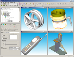
1. CAD models loaded in to 3G.author from different CAD modelers and FunctionalWizard window |
Geometries from different CAD sources (Picture 1, below, right) are easily readby3G.author. Bi-directional associativity with models issimultaneously maintained even from different CAD sources in the samedesignvalidation project (Picture 2). To facilitate collaboration, the CAD programdoes not have to beinstalled on the same desktopas 3G.author, providing additionalleverage for optimizing CAD and CAE licensing, which reduces the cost of softwareacquisition. When multiple configurations are created forvalidating a family of assemblies, performing what-if and trade studiesor running design optimization, only the corresponding clone in of theCAD model is changed in the 3G.author database. However, if a newassembly configuration created in the 3G.author database is to be savedto the original CAD database, it can be done from the program GUI.To speed the learning process, a new Function StudyWizard (Picture 1) can be used to start the validation of anassembly. When the type of analysis is defined, the Wizard guidesthe user through steps to input material properties, loading conditionsand assembly structural restraints. Material properties is readfrom the CAD program, manually input or edited, extracted fromuser-build material library or from popular Web-based database atwww.matweb.com (using Internet browsing functionality embedded in theprogram). After data input is completed, the Wizard begins thesimulation. The simulation stage automatically begins meshing,contact detection, FEA problem formulation and solution. When theresult is available, the Wizard switches to the post-processingmode. An advanced user can set up the problem and solve itwithout the Wizard.
The contact detection process is fully automated;however changing the geometry-based tolerance can control it. Forsolid assemblies, the automatic contact detection procedure detectspairs of faces from adjacent parts within a specified tolerance,effectively creating a default list of face-to-face contacts.This list can be updated and edited manually by adding or deletingpairs of geometric entities to set face-to-face, face-to-edge,edge-to-face and edge-to-edge contact. When working with ashell-body definition of a solid model, the automatic detectionprocedure detects four types of all possible contacts, using atolerance parameter specified for each shell body. A manualdetection option is available for more advanced users.
Modeling Real World Cases
|
2. Easy-to-use navigation with native CAD dimensions |
Mainstream design engineers can model real-worldassemblies with static and dynamic (harmonic, time-dependent andrandom) loading, and run trade and what-if studies as well as design ofexperiments. The computational performances of a variety ofdifferent algorithms in 3G.author are optimized for running multiplecase analyses quickly and efficiently. Access to feature-based, dimension-drivenCADassembly models allows an embedded spreadsheet to drive dimensions forwhat-if studies to validate a family of assemblies or run on-the-flyoptimization scenarios with different goals and criteria. Picturedemonstrates handling an assembly from different CAD sources in onedesign validation project (models from Inventor, Solid Edge,Pro/Engineer and SolidWorks). Picture 2 (above, right) shows the easy-to-usenavigation of native CAD dimensions.Problem solving capabilities of the program coverspecial cases of sheet metal and general cases of thin-wall typeassemblies. Special capabilities allow creation of shell-bodydefinitions of solid assemblies developed in a CAD program, forautomatic shell meshing and application of shell FEA solvers.Automatic detection as well as manual add-on operations withface-to-face, face-to-edge, edge-to-face and edge-to-edge contactsallows quickly constructing a valid shell body assembly and moving tothe modeling of shell-based solution physics, leads to quick validationof these CAD assemblies. With fully associative supported CADmodelers, parametric what-if studies and design-optimization can be runbased on native CAD dimensions and relations for sheet metal andthin-wall assemblies.The types of assemblies that can be modeled includethe default, which is a bolted/welded assembly modeled without anyadditional user interaction. More complex cases include:
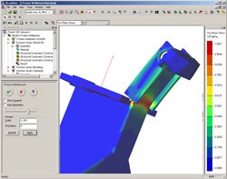
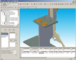
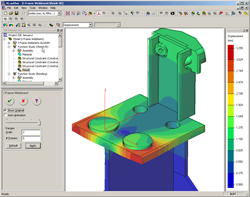
4. Result view of assembly stress analysis with non-linear contact conditions
All supported contact types can be used to modelreal-world assemblies with elastic small and large deformationconditions.Thermal contact types include ideal thermal contactand thermal resistance contact (in the 2005R2 release), they can beused for modeling thermal and coupled thermal-stress validation ofassembly for thermal linear, non-linear, steady-state and transientcases.
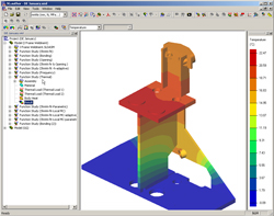
5. Result view of assembly thermal analysis
6. Result view of assembly Shrink-fit stress analysis
Underlying FEA Technology.
There are two general FEA approaches to assemblyanalysis. One approach uses compatible assembly meshing where thecontact faces mesh with topologically equivalent meshes with one-to-onemapped faces, edges and mesh nodes. The other approach usesincompatible meshing of the contact faces, which leads to an assemblymeshing process through independent meshing of the assemblyparts. This approach has essential advantages for simplifyingassembly meshing, making it faster, easier and more reliable formeshing an assembly with dissimilar size components. However, thefirst approach has some advantages in accuracy, especially for complexnon-linear contact cases. 3G.author incorporates both approaches,using incompatible meshing as the default choice.
The so-called mortar finite element formulation isused in both approaches, where unknown degrees of freedoms includedisplacement and interface traction (for stress analysis). Thisapproach is advantageous for assembly/contact analyze because it allowsdisplacements and contact forces to be simultaneously calculated infinite element formulation without differentiation of the displacementfield. This improves the speed of FEA approximationconvergence. The proprietary technology for fast solution ofresulting saddle points linear algebra equations allows quick andreliable assembly validation techniques, directed to handling big sizeassembly cases on an ordinary desktop.
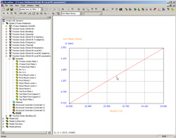
11. Shrnk-fit stress versa CAD dimension parameter plot
The combination of ease-of-use accuracy control andsimulation speed creates a new level of opportunity for design what-ifstudies and optimization: the user can better understand theeffect of geometry changes, distinguishing it from numerical errornoise when testing complex assembly cases.
For example, picture 11 shows how thestress of a shrink-fit assembly depends on the geometrical parameterdriving the initial parts overlap. Linear theory can predictlinear stress behavior. This particular case supports 3G.authoraccuracy, which allows highlighting the model physics withoutmisleading the designer with numerical noise from
digital simulation.
Customer cases of real-life assembly validationsinclude assembly with hundreds of parts and few millions of degrees offreedom FEA problems size, handled in mainstream desktopenvironment. The current version of 3G.author runs on families ofWindows-32 operating systems and system limitation of 2 GB RAM is theonly realistic limitation to FEA model size inherited by 3G.author, sofuture releases of the program for Windows-64 will push thecomputational envelope much further.

DE's editors contribute news and new product announcements to Digital Engineering. Press releases may be sent to them via [email protected].
Follow DEJoin over 90,000 engineering professionals who get fresh engineering news as soon as it is published.


About Us · Contact Us · Editorial Team · Advertising · Privacy Policy · Subscriber Services · © 2026 Digital Engineering 24/7 · Peerless Media