Using CFD to Take Back the Cup
The Kiwis are using ANSYS CFX fluid simulations to improve the sails,hull, and secret weapons of their sleek black America's Cup challenger.


Latest News
December 1, 2004
By Ian Jones

With tens of millions of dollars in sponsorship money on the line anddesign rules that change after each America’s Cup regatta, it’scritical for sailing team syndicates to have the best engineering anddesign wizardry at their fingertips. Scale models in water tanks andwind tunnels are fine, but when winning and losing are separated bymere seconds, the technology has to shine.
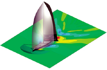
Left: Team New Zealand is using Ansys CFX-5 to help take the America’s Cup from the Swiss.
When it came time for Team New Zealand to defend its right to keep theAmerica’s Cup for a second time, the Kiwi design team decided it neededto take a closer look at the way wind and seawater flowed around itssleek black boats to improve the design of sails, the hull, andcritical hull appendages (HULA). To do that, the team’s boat designersturned to CFX-5 CFD (computational fluid dynamics) software from Ansys, Inc.
The Best Laid Plans
Fluid dynamics plays a critical role in the design of racing yacht hulls, especially at the 12-meter level (America’s Cup Class or ACC).The trick is coming up with a shape that takes full advantage of the power or lift generated by the sails without creating too much drag in the water; all the while staying within design limits set by the international sanctioning body. Small variations in hull and sail geometry can make the difference between victory and defeat, so theteam’s designers simulated hundreds of potential designs for the hull and its HULA to wring the last possible hundredth of a percent in performance out of their boats.
 Left: Simulations led to a lower center of
“CFD provides a substantial advantage over scale-model testing,” says Nick Holroyd, the Kiwi’s senior designer, “by allowing us to visualize air and water flow around the boat in order to understand why one design works better than another.”
As a result of using CFX-5, they lowered the center of gravity of the ballast bulb, increased the lift-to-drag ratio of the sails and trimmed hull drag by about a percent. That improvement, vast in the upper levels of yacht racing, gave the only non-USA syndicate to have successfully defended the Cup the confidence to do it again. Team NewZealand’s NZL-32 snatched the “Auld Mug” from Young America in 1995 and defended it with NZL-60 in 2000 in a convincing 5-0 win against challenger Prada. They were poised to best a Swiss Team led by their old skipper last winter with the new design changes, but structural trouble unrelated to the new hull shape plagued NZL-82 and they lost5-0.
The Kiwis have put the loss to Alinghi behind them and are so convinced of the benefits of CFX-5 that they are using it to come up with a new hull shape in their bid to take the 150-year-old Cup back in 2007.
HULAs and Hoops
Sails generate lift in a manner similar to an aircraft wing. Keels workto prevent the boat from moving sideways as a result of wind action onthe sails. In the wind tunnel or towing tank, designers measure bulkforces and observe the reactions of the sails and the pitching of thehull. The problem with physical testing is that the critical flows ofthe air and water are invisible, so little or nothing is learned aboutwhy performance is as it is. For that reason, design has long been atrial-and-error process requiring multiple prototypes that could costtens of thousands of dollars and take months to build and test.
The Kiwis, much to their credit and the consternation of others whocovet the Cup, have formed teams for relative shoestring budgets. Andwith the recent advances in CFD software, simulation helps them keeptesting costs under control while improving the design process.
Simulating the airflow over a sail is complex. With theparallel-processing CFX-5, though, Team New Zealand can solve a sixmillion node model in about 24 hours on a 16-processor Silicon GraphicsOrigin2000 server. (Compare that to building a physical model.)Improvements in the ANSYS code itself have likewise improved theaccuracy with which the highly turbulent flows around the sails, hull,and HULA can be predicted. Holroyd says one of the most significantimprovements is the ability to use the k-omega turbulence model inCFX-5 that provides significant advantages over the more commonk-epsilon model in resolving fine grids near the sail and hull. Forthis reason, the new model provides more accurate flow separationpredictions, which are important to accurate performance estimates.
“The flow visualization provided by CFX-5 provides much greater insightinto the design,” Holroyd says. “We can actually see how the air movesaround the sail, which helps us understand its behavior and leads torapid improvements. Simulation is so much faster that we can analyzedozens of different designs and determine which one provides the bestperformance in the time it would take to build and test a singlephysical model.”
Testing Bulbs
Some of the biggest improvements have been made in the design of theballast bulb, a torpedo filled with lead that hangs at the tip of thekeel. It balances the lift generated by the sail and keeps the boatupright. Typically, the bulb contains about 20 tons of lead andaccounts for about 80 percent of the boat’s weight.
The rules say that the bulb cannot extend more than four meters belowthe surface of the water. Within that constraint, designers want toposition the center of gravity of the bulb as low as possible in orderto properly balance lift forces on the sails. Yet squashing the bulbagainst the lower limit tends to increase its surface area. And that,in turn, increases drag. The resultant designs are closely guardedsecrets.
“In designing the 2003 generation boats, we started by testing sixbulbs in a wind tunnel,” Holroyd says. “We then replicated those testswith a high degree of accuracy using CFX-5’s k-omega turbulence model.Next, we simulated a wide range of different bulb shapes…we learnedthat if you make the angle at which the bulb narrows at its tail toosteep, an axial vortex will shear off the tail, wasting quite a bit ofenergy.”
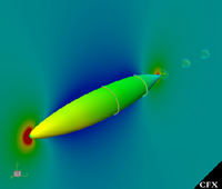
Right: Sea level surface contours for a yacht sailing downwind. Just oneof hundreds of simulations Team New Zealand is using to improve theshapes of sails and critical hull appendages in their challenge for the32nd America’s Cup, to be held in Spain in 2007.
Maximizing Sails
Designers have also focused heavily on improving the lift-to-drag ratioof the sails. The downwind sails are highly curved sections thatoperate at large angles of attack, typically 70 to 120 degrees to theboat’s direction, corresponding to 10 to 30 degrees to the chord line—astraight line from the leading edge of an airfoil to the trailingedge—of the sail. This means that the flow is typically separated overapproximately half of the sail area, creating a very difficult analysischallenge.
“We have discovered with CFX that these flows are unsteady due to thenature of the onset flow and also unsteady vortex shedding in thewake,” Holroyd says. “In an area that pushes the boundaries ofstate-of-the-art turbulence models, we have found that CFX-5 holds asignificant advantage over other codes.”
Since changes to the sail are possible up to the morning of the lastrace, team designers will continue to make parametric analyses ofcamber and draft position to find the most efficient shapes.
“After we have found the most suitable sections for given angles ofattack,” says Holroyd, “we will tackle the difficult procedure ofrelating the results back to the 3D design.
“In the America’s Cup, computer simulation has taken a leading role inthe design process,” adds Holroyd. “By saying that, I don’t want tominimize the role of physical testing, which is still critical inproviding more accurate measurements of lift and drag than CFD canprovide today. But CFD has taken us several steps beyond what we wereable to achieve in the past by allowing us to visualize flow velocityand pressure magnitudes, making it possible to improve the design at amuch faster rate.
“CFX-5’s superior tools for handling multiphase flows capture the wavedetail that we don’t see in other codes, so it’s the perfect tool forthe challenging analysis tasks we face,” says Holroyd. “As we put thefinishing touches on the 2003-generation boats, we were already workingon…2007. One of the key areas that we are testing is user-definedFortran subroutines to increase the accuracy of our analysis bysimulating the upward movement of the bow as the speed of the yachtincreases.”
It is too soon to know whether Team New Zealand’s secret weapons willget wet in this autumn’s first Cup regattas. But it will be ready tounleash new designs during the actual challenge off the Spanish coastbeginning in June 2007.
Ian Jones is head of the United Kingdom Technical Services Group forANSYS CFX. He has a PhD in flows over delta wings from the Universityof East Anglia. To contact him about this article, send comments to[email protected].
Company information
New ACC Design Rules
After the 2003 America’s Cup, the sanctioning body got together torevamp the rules. If you think the NHL’s continuous rules changes arefrustrating, just try to keep up with these. They happen after everyregatta. Here’s a sample:
• a drop of one ton in maximum allowable displacement
• an increase in maximum allowable draft of 100mm
• an increase in allowable downwind sail area of up to 8 percent
• an increase in working crew, from 16 to 17
• a general narrowing of permissible design parameters
The drop in displacement and increases in draft and sail area shouldmake for more excitement off the wind and better downwind passingopportunities. The increase in crew will help control the upped antefor speed and power. Cinched design parameters should keep the racingclose.
By 2005, a new version of the America’s Cup Class rule will bepublished. For older boats to comply, simple modifications will berequired to bring the hulls back into class. The biggest involveshanging the ballast bulb (with 2,000 lbs of lead removed) 100mm lower.But with up to 8 percent more sail, a longer spinnaker pole, and 4percent less displacement, boats will accelerate better, respond towind changes faster, and make better speed through the water. —JG
Subscribe to our FREE magazine, FREE email newsletters or both!
Latest News
About the Author
DE’s editors contribute news and new product announcements to Digital Engineering.
Press releases may be sent to them via [email protected].


