Helping design and engineering professionals discover, evaluate and specify technologies and processes that shorten the design cycle and enable success.

Design & Simulation Software Guide 2025
In this Special Issue, Digital Engineering presents its second annual guide to design and simulation software vendors.

Special Focus Issue: Artificial Intelligence in Simulation
In this Special Focus Issue of Digital Engineering, we look at the latest trends in integrating AI and machine learning with design and simulation tools. The issue includes features on synthetic data, open-source AI for modeling, AI-powered…
What was your workspace like in 1995? Your PC probably ran on 640K of memory, your graphics displayed on a 15-inch CRT, and if you were lucky, your company let you upgrade from Windows 3.1 to Windows 95. But whether your focus was mechanical finite element analysis (FEA) or air or fluid computational fluid dynamics (CFD), you mostly did your “real” work on a workstation, mainframe or distant networked Cray. A mesh of 50,000 elements was state-of-the-art, and CFD was pretty much the realm of Ph.D.s.
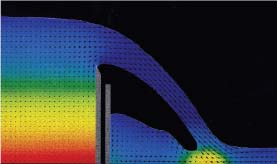 Simulation of water flowing over a weir (a low overflow dam) performed with a 1993 version of Flow Science FLOW-3D CFD software. Images courtesy Flow Science. | 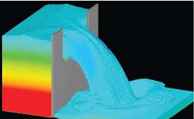 CFD simulation of water flowing through a sluice in a weir, done with the 2010 version of Flow Science FLOW-3D software. More detail is now included in the model and the results. |
The early 1970s and entire 1980s saw the birth and initial development of dozens of today’s well-respected analysis software packages. However, the mid-1990s witnessed explosive growth as the personal computer’s processing power, cache memory and graphics capabilities freed software developers from many computational bottlenecks.
FEA, Then and Now
Civil engineers led the way to developing FEAs. In the early 1940s, Richard Courant and Alexander Hrennikoff proposed two ways to discretize a continuous physical domain into subregions (finite elements, or FEs), approximating solutions to the complex partial differential equations (PDEs) defining mechanical vibration behavior.
By the mid-1950s, Ray Clough at UC Berkeley had coined the term “finite elements,” and co-authored a paper establishing a broader definition of FEs to model stiffness and deflection of complex structures. Aeronautical applications for FEA in the ’60s and ’70s expanded the algorithms to include beams, plates and shells, and NASA funded the development of what became NASTRAN code, as both linear and non-linear algorithms emerged.
Although the first general-use PCs came out in 1985, desktop FEA applications were severely limited by both processing speed and RAM, a situation that persisted until the mid-1990s but also spurred software innovations. Major commercial players emerged in the field, developing software that produced meshes with 5,000 to 7,000 nodes. However, users still had to greatly simplify their models and make many load and material assumptions.
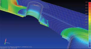 A typical structural mesh (c. 1990) generated by manually extruding elements in PATRAN 2.2. The bolted contact between parts in the assembly was created using bar/rod/spring elements and bolt-preload was created using a manually iterative process. This model took several weeks to complete and hours to run. Images courtesy NEi Software. |
|
Expensive processing time, charged by the minute, inspired existing companies and newcomers to write FEA codes for desktop PCs. For example, Dave Weinberg, founder and president of NEi Software (formerly Noran Engineering), used his NASTRAN experience at McDonald Douglas to create a version that would run on PCs instead of “billable” workstations. The result was NEi Nastran. Its basic pieces were running by 1986, and really advanced in the mid-1990s as RAM expanded and processing speed increased.
By 2000, a 3D shell model that would have taken a month to prepare in the 1970s could be done in a few hours. Algorithms could now handle surface contacts, sliding contacts and extreme (plastic) deformations, plus flexible and composite material properties.
Robert Taylor, an FEA expert at SIMULIA who studied under Clough at Berkley, points out that two other areas of development proved critical to the advancement of these tools.
“The ability to have graphical editors and to start solving larger models with interacting parts brought a lot of benefits,” he says. “We could visualize results all over the computer model, going beyond the limits of sensors on physical models.”
At the same time, parallel processing became available to the general user, allowing the possibility of even larger and more non-linear models.
Perhaps most significantly in the past decade, automating mesh generation—a task which often took longer than the solution itself—expanded FEA beyond the non-analyst expert. Preprocessors became part of the software package, and post-processors also simplified understanding and sharing results.
Lastly, making the entire process less expensive and more user-friendly (without diminishing its accuracy) meant suppliers, consultants and small companies could tap the power of FEA.
The Evolution of FEA
Over the past 15 years, enhancements to FEA programs have appeared so continuously it’s hard to keep track of results. Multiphysics applications have expanded far beyond the first fluid-structural interactions. Enormous increases in memory and processing power support analyzing models with more than a million degrees of freedom. And today’s computers even handle the explicit dynamics of relatively long-term events—as well as those taking place in milliseconds.
The variety and sophistication of element types has also greatly enhanced model fidelity. In fact, each of these improvements has helped skeptical engineers accept the value and validity of computer-based mechanical analyses to the point where industries such as the medical device world are moving to certification by simulation, a concept unheard of 20 years ago.
However, engineers being engineers, we know we’re never satisfied. Running codes on parallel processors is still tricky (do you get the same answer if you run it on one CPU or two?), and I/O bottlenecks still slow down the fastest solvers. In other words, there’s plenty of room for innovation.
Weinberg says he expects FEA will evolve to hide more of the internal computational complexities, so that users just input loads and conditions, yet obtain credible results. Taylor says he sees multiphysics expanding to include cyber-physical conditions, adding the effects of closed-loop software controllers into mechanical operations, and even getting down to the level of molecular dynamics as coupled to finite elements. He says he also believes that in the next decade, analysis and simulation in general will incorporate aspects of manufacturability and maintenance, allowing trade-off studies to cover a complete life-cycle analysis.
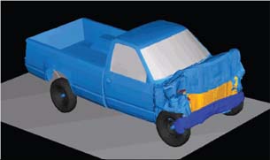 Although Abaqus FEA software produced good-correlation component models in the early 1990s, automakers’ full-body vehicle models were very coarse and used little FEA. Image courtesy SIMULIA. | 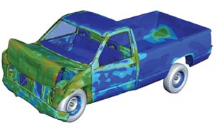 Current Abaqus FEA models from Dassault Systèmes’ SIMULIA can simulate full-body vehicle motion, crash, noise and vibration, rolling tires and crash dummies. Image courtesy of FHWA/NHTSA National Crash Analysis Center. |
From Ancient Waterworks to Modern Fluid Flow
Fascination with moving fluids is a recurring theme throughout history, from the waterworks of ancient Rome to da Vinci’s plans to cast his Horse statue from molten bronze. Mathematicians such as Bernoulli and Euler proposed fluid-flow equations that formed the basis of work done first by the Frenchman Claude Navier, and later by the Irishman George Stokes. The end result was the set of now-famous Navier-Stokes differential equations that are the basis of modern CFD.
Computers were the key to applying finite difference methods and finite volume methods for solving the closely coupled Navier-Stokes equations. The 1960s and ’70s finally witnessed solutions in acceptable timeframes for these non-linear equations (defining fluid flow, heat and materials transport), and commercial CFD codes overtook the use of proprietary in-house solutions.
David Gosman, founder and vice-president of technology at CD-adapco, began working with computer-based CFD in the late ’60s. He points out that working with Cartesian-coordinate-based geometry imposed great restrictions on accurate solutions. For example, any curved surface to be meshed could only be represented by a stair-step approximation. In 1987, CD-adapco developed tools to create body-fitted meshes, and by 1995, all CFD codes had been generalized in this way to handle different shapes of elements.
In the early days of personal computers, limited memory size also made it flatly impossible to work with highly detailed CAD geometry. Even as available RAM increased, Gosman found that management still preferred results from the traditional build-and-test approach. Eventually, the same improvements in memory, processing speed and user graphics that boosted FEA code usage tipped the scales to encourage more detailed, accurate and practical CFD analyses.
| NAFEMS as Visionary What group has its finger on the future of both FEA and CFD analyses? That would be NAFEMS, the international organization dedicated to promoting the effective use of engineering simulation methods such as finite element analysis, multibody system dynamics and computational fluid dynamics. Check out NAFEMS.org for its publication list and the activities of its technical and regional groups to find like-minded people shaping the future of analysis and simulation. |
CFD: The ’90s and Now
Aerospace and automotive engineers came to see CFD as a tool to thoroughly evaluate a wide variety of operating conditions impossible to test physically on complex designs. Still, many of the challenges with adopting CFD in the early 1990s were not directly connected to the analysis software itself.
For example, Gosman found that customers didn’t like spending extensive time on three necessary tasks outside of the solver: CAD data “cleanup,” meshing the model in proper detail and post-processing steps such as report generation. Time spent on the actual analysis was generally a small part of the process.
The next improvement, then, was to integrate these tasks and do them automatically, which opened the analysis process up to the concept of optimization. Including an optimization function in the design process—for example, by coupling a CFD package to an optimization code such as SIMULIA’s Isight—is very much a current growth area in this field.
As in the structural analysis world, multiphysics capabilities, whether in a single code or between well-communicating codes, are expanding throughout the CFD realm. Michael Barkhudarov, vice president of R&D at Flow Science, says hardware improvements, as well as advances in the capabilities of programming languages and software, have enabled developers to better couple FEA and CFD models. He notes that the new FSI capabilities have expanded to include such industrial processes as those found in micro-electro-mechanical systems (MEMS) and nanotechnology.
Whether one approaches multiphysics analysis by adding CFD capabilities to mechanical (FE) analysis or vice versa is still an open question. Either way, the analysis community must improve user education at both university and corporate levels to encourage using a coordinated set of tools.
CFD’s Future
As Gosman so puts it, “the boundaries are not very porous” among today’s typical CAD, FEA and CFD departments. “This (increased use) will happen, but not very quickly,” he says—pointing out, however, that one encouraging movement is greater access to parallel clusters and cloud-computing resources.
In the next decade, increased automation will be the dominating factor as CFD analyses move deeply into the design world.
“With the increased time constraints and market pressures for developing new products, the demand for fast, accurate and easy-to-use simulation tools is higher than ever,” Barkhudarov says.
More Info:
CD-adapco
Flow Science
NEi Software
SIMULIA
Contributing Editor Pamela Waterman, DE’s simulation expert, is an electrical engineer and freelance technical writer based in Arizona. You can send her e-mail to [email protected].

Pamela Waterman worked as Digital Engineering's contributing editor for two decades. Contact her via DE-Editors@ digitaleng.news.
Follow DEJoin over 90,000 engineering professionals who get fresh engineering news as soon as it is published.


About Us · Contact Us · Editorial Team · Advertising · Privacy Policy · Subscriber Services · © 2026 Digital Engineering 24/7 · Peerless Media
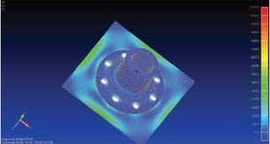 Today, a similar model of a fitting bolted to a pressure-vessel wall takes a few hours to build and minutes to solve using Siemens PLM Software’s Femap with NEi Nastran. Meshing is done automatically and includes more detail of the geometry. Bolts with preload and true surface-to-surface contact were generated automatically and solved in a single linear static analysis.