Helping design and engineering professionals discover, evaluate and specify technologies and processes that shorten the design cycle and enable success.

May 2026 Special Focus: Artificial Intelligence in Design and Simulation
In this Special Focus Issue, learn about the latest developments in the integration of artificial intelligence into engineering workflows.

Design & Simulation Software Guide 2025
In this Special Issue, Digital Engineering presents its second annual guide to design and simulation software vendors.
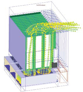 Figure 1: Original model without fan swirl. |
The advanced telecom computing architecture (ATCA) 3.0 specification has emerged as the industry’s hardware platform of choice and has already been widely deployed in network access layer applications. However, development of new blade sets has created the need for even higher capabilities, particularly for backplane bandwidth exceeding the 12.5GBps and thermal dissipation exceeding the 200 Watts per slot ATCA 3.0 specifications.
When Simclar Group, a technology-based electronic manufacturing services (EMS) company, set out to meet this challenge with its new TurboFabric scalable ATCA platform, the company ran into major challenges delivering the quantity and distribution of air needed to accommodate higher capacity switch fabrics.
Simclar engineers used thermal simulation to evaluate a wide range of fan configurations, plenum geometries, fan specifications, and air distribution methods. At Simclar, we succeeded in developing a platform that goes well beyond the ATCA 3.0 specification.
Expanding Upon the ATCA 3.0 Spec
ATCA needs to expand to cover aggregate layer and core network applications to deliver the performance improvements and cost efficiencies that service providers are demanding. By the same token, ATCA needs to seamlessly scale to accommodate new blade sets as bandwidth demands increase over time.
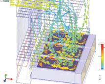 Figure 2: Adding fan swirl provides more realistic simulation. |
These requirements pose a significant technical challenge. Network core and aggregation layer equipment and next-generation scalable blade sets all require higher capacity switch fabrics than those currently offered by the ATCA 3.0 specification. While the specification accommodates a variety of data fabrics, the backplane for each fabric is based on an architecture featuring four parallel lanes of 3.125Gbps for transmit and receive and provides limited scope either to support high-end equipment or future upgrades. Furthermore, the ATCA thermal dissipation specification of 200W per slot is insufficient to cope with the increased power requirements that will be demanded by a truly scalable solution.
Simclar Group accepted the challenge and set out to design a range of high-bandwidth, highly scalable ATCA platforms to meet these requirements. The company used advanced printed circuit board (PCB) materials, connectors, vias, and stack designs to push the performance limits of copper backplane channels up to 40Gbps. The company’s most advanced backplanes have been modeled, simulated, tested, and verified for end-to-end channel performance from output of driver to input of receiver to provide up to 10 Gbps NRZ signaling capability per differential pair.
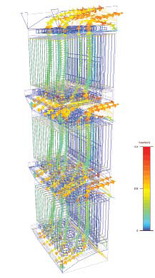 Figure 3: Simulation of final design shows air drawn in at front and exiting at rear. |
But solving the signal integrity challenge fixed only one part of the problem. With higher speed blades comes the added burden of increased power consumption and heat dissipation, which in turn requires increased cooling. This problem cannot simply be solved by adding more powerful fans. Telecom platforms must meet strict network equipment-building system (NEBS) noise requirements. And running fans at high rates to provide better cooling increases noise and also reduces fan life.
Original Thermal Design Falls Short
The first phase thermal design for the TurboFabric platform was developed using engineering calculations and physical testing. The design was reasonable but fell short of performance requirements. Significant physical testing had been performed but provided little guidance as to the root cause of the problem because temperature and airflow measurements were obtainable only at a few discrete points.
The ATCA specifications provides for four different thermal classifications: B1 at 25CFM per slot, B2 at 30CFM per slot, B3 at 35CFM per slot, and B4 at 40CFM per slot. The specifications also provide that airflow must be distributed evenly over each board. The boards are divided into four zones running parallel to the direction of airflow and each zone of the board must deliver a minimum of 20 percent of the total volume of airflow over the board. Besides airflow and fan life, the thermal design is also constrained by the need to minimize openings in order to meet electromagnetic compatibility (EMC) requirements. The available internal space is limited by ATCA form factor requirements.
I was brought into the project because of my thermal design experience, extending back to the early 1990s. Thermal simulation is like having x-ray vision. It lets you see inside the box to look at airflow, pressures, and temperatures at any point. A single thermal simulation gives you a detailed understanding of what is going on inside the box and helps you quickly identify the root causes of the problem.
In the 15-plus years that I have been involved with thermal simulation, I have developed a strong preference for Mentor Graphics’ Flotherm software. Its user interface is very intuitive, making it possible to rapidly create and manipulate simulations. Flotherm’s visualization editor provides powerful tools for displaying and animating results. This makes it much easier to understand problems and to explain to others why the design changes that you are recommending are necessary. In addition, many customers use Flotherm, allowing potential sharing and integration of models.
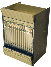 Figure 4: Simclar TurboFabric platform |
Accounting for Fan Swirl
In this application, the initial Flotherm simulation (run on an Intel 6420 dual-core processor at 2.13GHz with 3GB RAM and Windows 2000) did not correlate with the test results of the design. I used the Flotherm Axial Fan SmartPart to model the fan. The Axial Fan SmartPart substantially reduces modeling and solution time by providing a behavioral representative of the fan that eliminates the need to model its detailed geometry and motion.
In this initial simulation run, I set up the Axial Fan SmartPart in the default mode, which does incorporate fan swirl. Fan swirl occurs when the airflow comes off the rotating airfoils at an angle to the face of the fan. Fan swirl does not affect total airflow but changes the distribution of airflow, particularly the regions of high and low velocity. When I turned on fan swirl the simulation results then matched up closely to physical testing. The results confirmed that airflow would not meet the company’s aggressive design goal of 50CFM per slot, which is well above the ATCA 3.0 standard.
Simulation gave me the freedom to consider a wide range of alternative designs by letting me evaluate their performance quickly and with no hardware costs. I simulated a “push” airflow system, with the fans located below the cards; a “pull” system, with the fans located above the cards; and a “push-pull” system, with the fans located before and after the cards. I also looked at different ways of allocating the available space to plenums at the inlets and outlets. A primary goal was to reduce pressure drop as much as possible. Lower pressure drop helps reduce fan swirl and enables the fan to run more slowly to help meet noise requirements. This meant taking a look at air filters and grilles. With pressure drops minimized, we were then able to determine an optimal cooling-fan design.
Selecting the Best Fan
The reduction in pressure drop inside the chassis changed the type of fan that would provide the best performance. The fan curve defines the output of the fan in CFM relative to the static pressure it sees. Fan curves are usually characterized by a smooth slope starting at zero static pressure with flow increasing as static pressure is reduced. At some point this curve peaks and the static pressure is reduced at the start of the surge or stall region of the curve. Except in rare special cases the fan should not be operated to the left of this peak, often called the knee of the fan curve, because this area is very unstable—small changes in static pressure may lead to large changes in flow. The ideal operating point is usually just to the right of the knee. I evaluated multiple fans and selected one that operated very efficiently at the static pressure generated by the optimized chassis design.
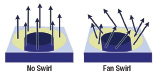 A fan model with and without fan swirl. |
After we identified the ideal fan, I ran a new simulation that showed that we were now meeting the design specification by delivering more than 50CFM to each slot and also meeting the 20 percent air-distribution requirement. The simulations also allowed us to evaluate a number of build variants. We made the chassis design modular so that fan configuration could be switched between push and push-pull, and the size of the plenums could be adjusted. The result is that the TurboFabric not only meets the thermal requirements of the foreseeable future, but can be upgraded to provide a future-proof solution for telecommunications equipment manufacturers.
More Info
Mentor Graphics Corp.
Marlborough, MA
Simclar Group
Dunfermline, UK
Dave Watson is the thermal design team leader at SIMCLAR Group. You can send comments about this story to [email protected].

DE's editors contribute news and new product announcements to Digital Engineering. Press releases may be sent to them via [email protected].
Follow DEJoin over 90,000 engineering professionals who get fresh engineering news as soon as it is published.


About Us · Contact Us · Editorial Team · Advertising · Privacy Policy · Subscriber Services · © 2026 Digital Engineering 24/7 · Peerless Media