

Latest News
June 1, 2006
By DE Editors
Solid Edge 19 Launches
New relationship types between gears and motors as well as new explode and motion simulation capabilities are some of the enhancements in Solid Edge version 19 that UGS Corp. (Plano, TX) highlights.
Solid Edge v19 has “hundreds of enhancements requested by our small and mid-size customers,” said Adrian Scholes, director of Solid Edge marketing for UGS in a briefing with DE. Further, Mr. Scholes pointed out various features and capabilities that enable designers, manufacturers, and global partners to create, share, and manage design data.
Solid Edge v19 offers full-motion simulation capabilities. Here, engineers can now define relationships between different motion drivers, such as gears, pulleys, hydraulic cylinders, and motors. Next, engineers can send their suppliers and customers motion studies of their product/design, showing how that product/design is intended to function. Additionally, v19 offers dynamic documentation tools that let engineers capture, modify, and animate how parts are assembled and disassembled.
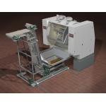 |
| Solid Edge Version 19 from UGS Corp. |
Other collaboration enhancements in Solid Edge v19 include the JT standard file format, which enables the sharing of 3D part and assembly design across multiple CAD platforms, and PMI (Product Manufacturing Information) functionality. The latter enables v19 to produce 3D-annotated designs that are compliant with such standards as ASME Y14.41, meaning that Solid Edge models can now serve as single digital representation containing all product data.
Solid Edge’s sheet-metal design capabilities offer such new features as corner stiffeners, cross breaks, and hems. Other features in Solid Edge 19 include bend tables, enhanced workflow for AutoCAD data, and WYSIWYG import of DXF/DWG files that includes matching color schemes, fonts, styles, and backgrounds. Also, with the introduction of v19, Solid Edge is available in a 64-bit edition to speed the creation of massive assemblies and associated drawings.
For full details including online AVIs, go to the Solid Edge pages on the UGS website.
DE has learned that Sony Manufacturing Systems America, Inc. (SMSA; Lake Forest, CA) has discontinued all sales efforts relating to its stereolithography (STL) line of products known as Solid Creation Systems and has been closing down its North American STL operations since May.
SMSA also offers digital instrumentation, measurement systems, surface mount equipment, and precision microscopes. None of these product lines appear affected by this development.
Solid Creation Systems were first available in the US in the fall of 2003 under the name Solid Creator. The discontinuation of the sales efforts, effective immediately, applies to Solid Creation Systems hardware, software, third-party postprocessing equipment, and related hardware, software, and materials, according to industry consultant Terry Wohlers of Wohlers Associates (Fort Collins, CO).
“After nearly three years of presence in this part of the world,” wrote Wohlers in response to a DE e-mail inquiry, “the company had sold few systems. The machine, called the Solid Creation System, is based on mature technology that was first commercialized in 1989. The hardware is rock solid and builds excellent parts, but the system software was never fully finished. It was one of several obstacles the company faced in penetrating the U.S. market.”
“Sony’s entrance into the U.S. market was welcomed, since it promised alternatives, technology advancements, and competition in the rapid prototyping industry,” said Todd Grimm, founder and president of T. A. Grimm & Associates, Inc. (Edgewood, KY) and the author of the User’s Guide to Rapid Prototyping. Grimm was responding to a separate inquiry from DE. “While the Solid Creation Systems had only marginal success, Sony’s decision to pull out of rapid prototyping is disappointing because the industry now has lost a driving force for advancing the technology and spurring further industry growth.”
At press time, no official statement from SMSA or Sony USA was available on either the SMSA site or the Sony USA site. DE will continue to monitor this story for further developments.
SPECviewperf 9 is a new version of the performance evaluation software from the SPEC/GPC’s OpenGL Performance Characterization (SPECopc; Warrenton, VA) project group. Standard Performance Evaluation Corp. (SPEC) is a nonprofit corporation formed to establish, maintain, and endorse a standard set of benchmarks for high-performance computers.
New viewsets are based on traces of UGS Teamcenter Visualization Mockup, a conceptual design application, and UGS NX 3, a CAD/CAM application. Both new viewsets use very large and complex models: up to 11 million vertices in the Teamcenter Visualization Mockup viewset, and 30 million vertices in the NX 3 viewset.
A significant change in version 9 is the use of glDrawElements instead of glArrayElement within the restructured Maya viewset. There are also new features that enable it to more closely mirror typical application performance. Visit SPEC’s website for initial performance results and free downloads.
In the 1980s, when PDM was still mostly a tool written in house for individual engineering departments, Scott Paper approached Quakertown, PA-based Synergis Software, and asked for help in managing a vast number of AutoCAD files for which revisions needed to be controlled. Synergis wrote an application for them. A few years later, it did the same for M&M Mars—complicated by management fear that some designers were leaking information to outsiders. The new system needed to be able to audit use of files. It did, the miscreants were caught, and Synergis had the seeds of what grew into a system called Adept.
The company calls Adept a document and data management system, but in essence it’s a PDM system that works with the full range of Autodesk mechanical and AEC design products as well as with SolidWorks. And with remote collaboration and workflow tools, Adept appears to be making developmental inroads toward PLM.
Todd Cummings, vice president of Product Development for Synergis, says that the system “is now an 80-20 solution.” That is, he explains, 80% is an out-of-the-box commercial program developed by one cadre of developers, while another development group handles customized solutions, geared primarily to extending functionality and linking Adept to other software in use by clients.”
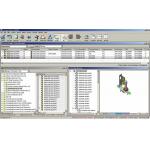 |
| The Adept document and data management system from Synergis Software. |
Both Autodesk and SolidWorks offer their own PDM tools. When asked whether Adept runs alongside Vault and PDMWorks, Cummings says that Adept, currently in use in more than 500 mostly small to midsize organizations, goes beyond those solutions, and its users want more functionality. “Users don’t need to have the CAD system to explore the product catalog,” he says. “They get a view that’s similar to a Windows-based CAD feature tree, in which they can see parts and where those parts fit into assemblies—along with such data as materials.”
Adept incorporates an open source Sequel database, and works with Microsoft Sequel servers, as well as with some Oracle enterprise clients. Although designed for the SMB market segment, the program has also been implemented by some larger customers who like its capabilities. Cummings reports that typical customers have 15 or 16 licenses, but Adept’s largest installation has about 500 seats.
Synergis started by helping clients manage thousands of documents, moved to interrelated parts drawings, and then to solving problems of connecting design data to other business systems, including Microsoft Office documents. Companies that are growing organically and want a similarly built PDM approach may want to check out Synergis Software.—Louise Elliott
Ansoft Corporation (Pittsburgh, PA) says that both Nexxim v3 and Ansoft Designer v3 are available for the Red Hat Enterprise Linux v.3 and Sun Solaris 8 and 9 operating systems. The release of Nexxim and Ansoft Designer for Linux provides an alternative to the previously released Microsoft Windows versions and leverages the growing popularity of Linux as a viable engineering platform, says Ansoft.
Nexxim is the company’s circuit simulation software for high-performance IC design and signal-integrity analysis. Ansoft Designer provides an integrated schematic and design management front-end for complex analog, RF, and mixed-signal applications.
In addition to Linux support, Nexxim v3 adds phase and time-variant noise, autonomous source harmonic balance, and integration with Cadence ADE/Spectre RF. Adding accurate phase and time-varying noise analyses to Nexxim is critical to the full characterization of communication ICs. Ansoft says the ability to include both driven and autonomous sources with a single harmonic-balance simulation dramatically expands the accuracy and detail with which complex transceiver circuits can be analyzed. They add that Nexxim allows engineers developing large and complex analog/RF designs to simulate accurate transistor-level time- and frequency-domain performance directly from within the Cadence ADE design framework. This leverages existing design-flow infrastructure, foundry models, and circuit-related intellectual property.
Ansoft Designer v3 offers expanded Solver on Demand capability and new design-verification technology to speed the design process of RF systems and RF/analog ICs and to increase the accuracy of signal-integrity studies. With Ansoft Designer v3, engineers can capture high-frequency parasitic behavior directly in their circuit simulation and apply that knowledge to design optimization and verification. Moreover, extending the Solver on Demand technology to include HFSS, Ansoft’s 3D full-wave electromagnetic-field simulation software, allows engineers to perform parametric design optimization with GHz-accurate, full-wave extraction.
Creative Products Company has announced it will manage the sales, marketing, and product development of the Metrolosys inspection software product line, including Metrolosys v9.5, which transforms any machine tool into a coordinate measuring machine (CMM). Creative Products Company specializes in manufacturing software development, and offers CNC machining and high-end laser engraving services.
According to a press release, Creative Products Company will continue to support the integration of the AIMS (advanced integrated mathematical system) Metrology Kernel within the Metrolosys inspection software. Jointly developed by The Boeing Company and Metronor Group, AIMS enables paperless manufacturing and seamless, bidirectional sharing of CAD geometry, inspection plans, and measurement data between industrial hardware and software platforms.
Metrolosys allows manufacturers to use any probe-ready CNC milling machine in the same way they would use a CMM. It supports ISO 17025, ASME B5.54, and NIST traceability standards. Metrolosys provides independent volumetric error mapping, advanced high-speed probing methods, and automatically generates Inspection G-code.
According to the company, Metrolosys 9.5 has helped reduce machine-tool downtime up to 75 percent at manufacturing companies. A user can program a CNC machine using a touch probe to measure a part, and can drastically reduce the process to less than 10 keystrokes when creating the part inspection G-code probing program. Metrolosys enables the machine tool to perform the inspection without tearing down the job for first article inspection or any other inspection requirement. After machining a part, it is ready for in-place inspection, thus contributing to the lean manufacturing process. CMM-type alignments of the machine tool to the machined part and its corresponding 3D CAD model are easily accomplished using Metrolosys.
UGS Corp. and Siemens Automation & Drives (A&D) Group recently announced a partnership to deliver a software solution that promises to enable companies to design and program manufacturing facilities for products still in development. Anticipated benefits will be significant acceleration of product introductions and higher quality production line ramp-up.
UGS and Siemens A&D already had worked closely together, due to Siemens’ long relationship with Tecnomatix prior to its acquisition by UGS. Al Hufstetler, vice president of Tecnomatix Marketing for UGS, says, “Nowadays, though, PLM is the real driver of business. The new partnerships aim to help customers get much closer to concurrent product development and plant automation. Companies can approach that objective by bringing manufacturing knowledge into the Teamcenter environment at the point where the product design solidifies.”
The software, which UGS and Siemens expect to launch in 2007, will enable companies to develop a new product, define its digital manufacturing environment, and design the set of plant floor automation equipment, all simultaneously. A company designing a plant or parts of it will be able to enter process knowledge into Teamcenter, which can be accessed by both design and manufacturing, making it possible to leverage manufacturing knowledge early in the product lifecycle.
“Manufacturing follows rules,” Hufstetler says, “and if we can bring the information that governs how to build products closer to design, then when developers solidify a design, they can bring manufacturability to it—including plant floor specifics. After all, if the company can capture knowledge and design a manufacturing facility digitally, it can capture the programmatic features of that design and finish product development to accommodate them—automatically.”
Hufstetler adds that while no solution ever resolves 100% of possible issues, bringing the product lifecycle stages of design and manufacturing closer to each other will reduce product launch time significantly.
At the moment, UGS and Siemens are looking for early adopters, companies with similar ideas and the same aim of bringing the virtual and real worlds together. “We want the ideas of interested manufacturers, want their participation in proof-of-concept studies, and possibly a few pilots by the end of this year.”
For more information, please check out ugs.com and siemens.com.
—Louise Elliott
Many alert subscribers reported to us that some of the results in the benchmark results chart that accompanied David Cohn’s review of the Dell Precision M65 and M90 notebook computers, “Power to Go” (June DE, click here to see the article), seemed odd. They were right.
A transcription error—a.k.a, fingers coupled with cut and paste—caused a number of the results to be incorrectly duplicated. A corrected XLS file of the entire benchmark results can now be downloaded from the online version of this article.
Thank you to all the subscribers who took a moment to write. We regret the error.—DE
Subscribe to our FREE magazine, FREE email newsletters or both!
Latest News
About the Author
DE’s editors contribute news and new product announcements to Digital Engineering.
Press releases may be sent to them via [email protected].


