Helping design and engineering professionals discover, evaluate and specify technologies and processes that shorten the design cycle and enable success.

May 2026 Special Focus: Artificial Intelligence in Design and Simulation
In this Special Focus Issue, learn about the latest developments in the integration of artificial intelligence into engineering workflows.

Design & Simulation Software Guide 2025
In this Special Issue, Digital Engineering presents its second annual guide to design and simulation software vendors.
Editor’s note: In his April 2012 article, the author provided an overview of the process described in step-by-step detail below. Please see that article here.
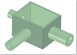
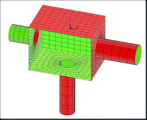
SpaceClaim 1: We start out with a thin-walled part created by another modeler and imported into SpaceClaim. For the sake of simplicity we assume that all undesired rounds, holes and cut-outs have already been removed, leaving us with the part shown below
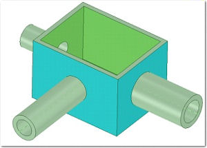
SpaceClaim 2: Switch from Design to Prepare, click on Midsurfaces and select the box as shown below
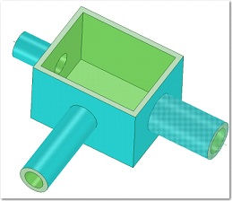
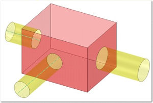
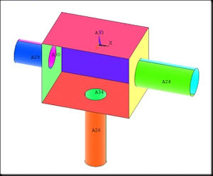
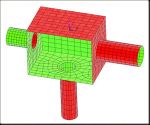
SpaceClaim 3: With Midsurfaces still active, click on the Add/Remove Faces tool and add the three pipes to the selection. If what you see on your screen looks similar to the Figure below (left) click on the Complete tool to finalize the midsurface extraction. The result should look similar to the Figure below (right)
 |  |
|---|
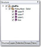
SpaceClaim 4: Delete all 3D solids, that is, if you check the Structure tree, it should indicate that the part consists of four surfaces only, viz.
SpaceClaim 5: Export the part to a neutral geometry file, say IGES.
ANSYS 1: Now we are off to ANSYS. First, we import the geometry using the sequence
File > Import > IGES
ANSYS 3: To make sure that the model has no gaps nor overlaps use the sequencesPreprocessor > Modeling > Delete > Volumes Only
Preprocessor > Modeling > Operate > Boolean > Glue > Lines > Pick All
Preprocessor > Modeling > Operate > Boolean > Glue > Areas > Pick All
Preprocessor > Modeling > Operate > Boolean > Overlap > Lines > Pick AllPreprocessor > Modeling > Operate > Boolean > Overlap > Areas > Pick All
ANSYS 4: Choose a thin shell element from the library using the sequence
Preprocessor > Element Type > Add/Edit/Delete > Add > Shell > Elastic 4node 63ANSYS 5: Define the shell element “real constants” using the sequence
Preprocessor > Real Constants > Add/Edit/Delete > Add > OKThat brings up the real constants window
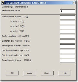
In the simplest case scenario (shell with constant thickness) only one value need be entered in the first box. If the thicknesses of the box and the pipes are not all the same then we need to define more than one set and assign each one to the respective portion of the mesh.
ANSYS 6: Define the material properties using the sequence
Preprocessor > Material Props > Material Models
which will bring up a window titled Define Material Model Behavior
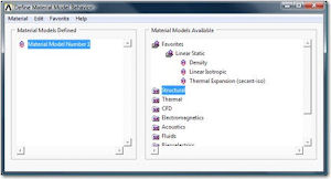
Expand the Favorites folder and click on Linear Isotropic to bring up the window
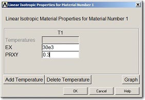
where the numerical values for the modulus of elasticity (EX) and Poisson’s ratio (PRXY) may be entered. We assumed the material to be structural steel and entered for EX=30000 (ksi), and for PRXY=0.3.
ANSYS 7: Use the sequence
Preprocessor > Meshing > Size Cntrls > ManualSize > Lines > Picked Linesin order to define size controls for the mesh generation (we used ten divisions per line) and then proceed to create the mesh using the sequence
Preprocessor > Meshing > Mesh > Areas > Pick All
The result is shown in the figure below.
Note that certain symmetries of the part geometry have not been preserved in the mesh which, in turn, may adversely affect the accuracy of the results obtained by the analysis.
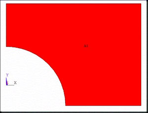
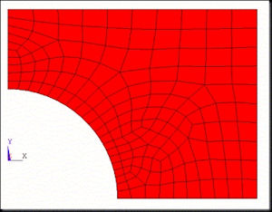
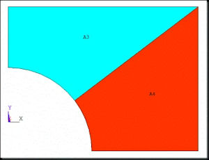
A better mesh is obtained by splitting all faces in question into three- or four-sided regions. While it is outside the scope of this tutorial to get into too much detail about meshing it seems appropriate to briefly note the difference between a free and a mapped mesh. A free mesh may be applied to any region of arbitrary shape as shown in the figures below.
 |  |
|---|
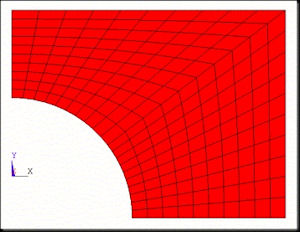
Whereas a mapped mesh may be applied only to three- or four-sided regions, viz.
 |  |
|---|
Going now back to our thin-walled part, the splitting of the surfaces may be done either in ANSYS or in SpaceClaim. Personally, in terms of manipulating geometry I find the latter considerably easier to work with than the former.
 |  |
|---|
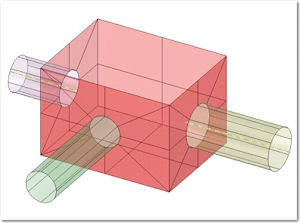
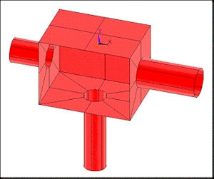
The figures above show, respectively, the model exported from SpaceClaim (left) and the model imported into ANSYS (right). The obtained mesh in this case is shown in the figure below.
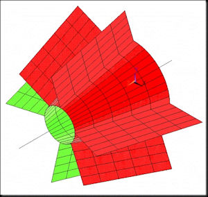
As a second example consider now the thin-walled part shown in the figure below
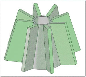
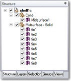
Proceeding as before, we extract all midsurfaces which leaves us with the solid shown below
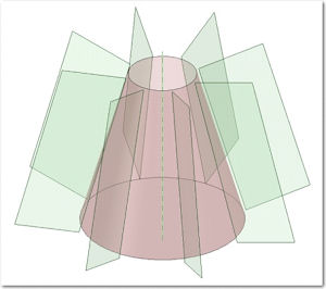
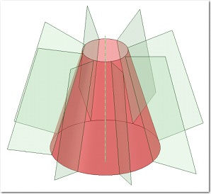
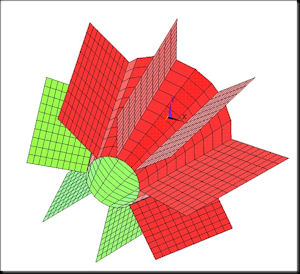
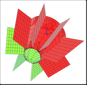
Noticing that the fins are a) too long and b) not connected with the cone we take care of both issues in SpaceClaim using the Pool tool. The resulting surface solid along with its structure tree is shown below.
 |  |
|---|
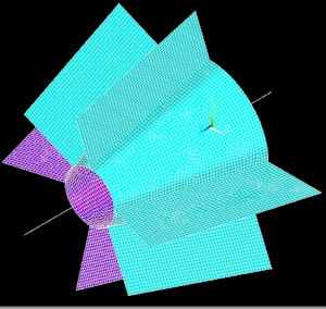
Importing the geometry into ANSYS and creating a mesh of SHELL63 elements leads to
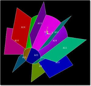
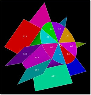
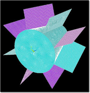
Upon closer examination we realize that the above created mesh is basically useless due to improper connections between elements. The reason for that is that the entire cone is represented as a single surface. Hence, we go back to SpaceClaim and subdivide the cone accordingly
 |  |
|---|
Depending on the kind of analysis we intend to perform it may be necessary/sufficient to use a coarse mesh,
a locally refined mesh,
or a fine mesh
 |  |
|---|

DE's editors contribute news and new product announcements to Digital Engineering. Press releases may be sent to them via [email protected].
Follow DEJoin over 90,000 engineering professionals who get fresh engineering news as soon as it is published.


About Us · Contact Us · Editorial Team · Advertising · Privacy Policy · Subscriber Services · © 2026 Digital Engineering 24/7 · Peerless Media