Helping design and engineering professionals discover, evaluate and specify technologies and processes that shorten the design cycle and enable success.

May 2026 Special Focus: Artificial Intelligence in Design and Simulation
In this Special Focus Issue, learn about the latest developments in the integration of artificial intelligence into engineering workflows.

April 2026 Special Focus Issue: Generative Design
In this Special Focus Issue, Digital Engineering takes a look at how generative design solutions can be used across different types of design problems and with a variety of manufacturing approaches to accelerate design space exploration, and…
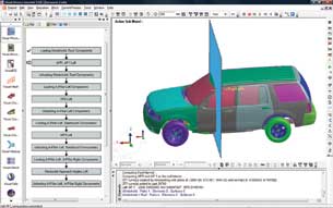 Figure 1. |
As part of its operations, IAC receives geometric studio design surfaces for interior components from automotive original equipment manufacturers (OEMs) in the form of a computer-aided design (CAD) files. The company’s engineers use this information to design parts and meet federal crash test requirements. The OEMs are responsible for testing the systems to ensure they comply with Federal Motor Vehicle Safety Standards (FMVSS) for instrument panels (IPs) and upper interior components.
Federal Safety Standards
FMVSS 201 states that when an area of the instrument panel is hit by a 6.8 Kg, 165 mm diameter head at 19 Km/hr, the deceleration of the head should not exceed 80 g continuously for more than 3 ms. FMVSS 201U provides a similar requirement for upper interior components, such as the pillar trim, headliner, and grab handle, but it is expressed in terms of Head Injury Criteria (HIC(d)) of less than 1000. European ECE-21 and EEC 74/60 regulations are similar, except they specify an impact speed of 24 Km/hr.
The OEM or supplier is responsible for identifying the zone in which the passenger’s head may contact the IP and upper interior components (Figure 1). FMVSS 201 defines the head-impact area as the nonglazed surfaces of the interior that are statically contactable by a 6.5-inch diameter spherical head form, having a pivot point to top-of-head adjustment ranging from 7.36 to 7.40 m. This process is normally undertaken to cover the range of dummies (5th%, 50th%, and 95th %).
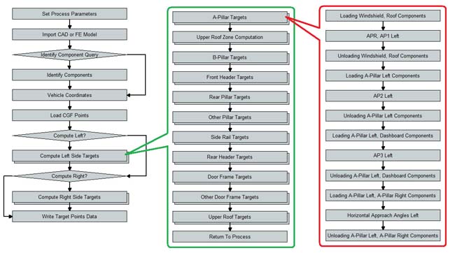 Figure 2. ESI’s system automatically visualizes the workflow for head-impact analysis. |
The regulations state that all points in the impact zone must meet the 80 g deceleration requirements. The OEM or supplier must select the number of representative points for simulation that fall in the calculated head-impact zone. For each impact point, the OEM or supplier must determine the impact angle of the head with that point. The regulations state the angle should be determined by positioning a line vertically at the seating reference point, the rearmost normal position where the hip contacts the seat and rotated down toward the instrument panel until contact occurs. The intersection of the perpendicular with the panel assembly surface is the location of the point of impact, and the direction of impact is taken along the perpendicular.
The Manual Process
In the past, to assess the performance of interior systems, IAC analysts had to perform a lengthy manual process in a CAD system to calculate the potential head-impact zone, define impact points and approach angles, create input data for crash simulation, and generate a report from the simulation results. As part of this process, they selected a series of points in the impact zone and computed the impact angle for each point. The analysts positioned the head form at the impact point, assigned it an initial velocity, created contacts between the head form and IP, created input-output control cards, exported LS-DYNA input data, read the LS-DYNA result files, and created an electronic report of the analysis results.
|
IAC’s engineers were dissatisfied with this process because it tied up highly skilled analysts for a considerable amount of time. In addition, it often was a bottleneck in the delivery schedule.
Finding a Better Way
The analysts evaluated several possible solutions for automating the manual process. A number of vendors offered the ability to develop automated workflow around different CAD and simulation solutions. IAC’s engineers decided that ESI offered a flexible solution that enabled them to develop a script that automatically determines the impact zones, selects impact points, and calculates impact angles at a studio released CAD level very early in the product development cycle.
“ESI’s Visual-Process solution made it possible to automate the entire simulation setup and reporting process,” said Arun Chickmenahalli, Computer Aided Engineering Manager for IAC. “This substantially increased the time-savings that we were able to achieve in this application.”
Developing an Automated System
IAC worked with ESI to develop an automated system for this process. The solution is based on ESI’s Visual Decision Support System (VisualDSS), which is designed to build and manage simulation models for multiple domains, automate processes and workflows, manage simulation content and data, and support knowledge-based decisions and automated reporting (Figure 2). The environment captures and automatically executes simulation processes, using wrappers for popular simulation and CAD tools. Templates are defined, using the Python scripting language, and the task-execution sequences can be described through a visual interface. The templates library can be searched, using filters and defined criteria for re-use in new projects.
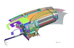 Figure 4. The automated analysis also calculates target points and approach angles for head impacts. |
Another key component in the application is ESI’s Visual-Crash Dyna, which provides an environment that enables both automated and manual creation of LS-DYNA models. Visual-Crash Dyna enables graphical creation of an LS-DYNA input deck, modification and deletion of contacts, materials, constraints, control cards, and crash entities. Visual-Crash Dyna modification tools help correct errors before the model is submitted to the solver. Visual-Crash Dyna is incorporated in the automated process, and analysts also use it to check and tweak the input deck.
Script Operation
IAC analysts defined the inputs and outputs required to execute the sequence of codes to automate the entire crash simulation set-up and reporting process. ESI developed the application’s core by using IAC’s expertise and best practices. The actual process begins when the user inputs data, such as the seating reference point and the center of gravity of the head, and reads the CAD data from Dassault Systemes CATIA, Siemens PLM NX CAD software, or any other suitable CAD format. The script automatically scans the CAD file by moving the head model as specified in FMVSS regulations to identify the impact zones.
The script selects impact points based on criteria provided by the analyst/OEMs (Figure 3). For example, one OEM might specify that impact points be selected every 100 mm, starting with the center of the impact zone. The script computes the impact angle for each point and positions the head form at the impact point (Figure 4). The initial velocity is assigned to the head form as defined in the regulation. The script then creates LS-DYNA contacts between the head form and the instrument panel interior and among the instrument panel interior components (Figure 5). Afterward, the script creates the LS-DYNA input-output control cards. An experienced analyst reviews the input data and sometimes makes changes, using the Visual-Crash Dyna environment.
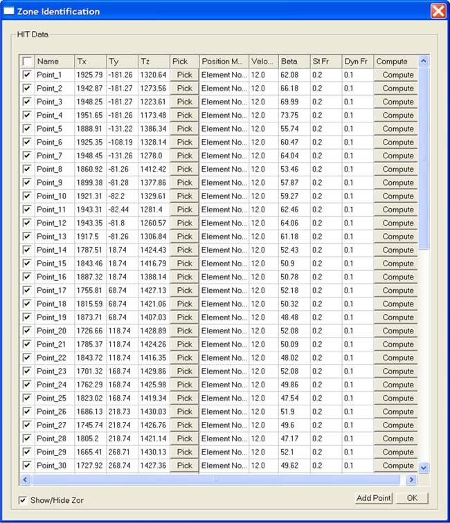 Figure 5. The head impact analysis identifies contact points on the instrument panel. |
For example, an analyst may move an impact point, perhaps to a location on the IP, opposite a bracket, which may be particularly sensitive in terms of causing injury. The analyst directs the script to export the LS-DYNA input data and submits it to the solver. When the solver has completed its run, the script captures the results. The analyst then runs the report-generation command. The script captures the results and formats them as defined by a template created by the analyst. The software can produce reports in HTML, PDF, and PPT formats.
The Benefits
“The Visual-Process script has substantially improved our process to comply with FMVSS 201 regulations,” says Chickmenahalli. “Unlike other solutions that we looked at, Visual-Process was able to automate the complete end-to-end head-impact simulation process. As a result, we have been able to reduce by four weeks the time needed to complete the simulation process required to comply with regulations, while increasing the accuracy of the simulation.
The time savings help IAC bring products to market faster, reduce its engineering costs, and enable its analysts to complete more projects. The improvements in accuracy are impossible to quantify at this time but are also substantial. The definition of impact zones, selection of impact points, calculation of impact angles, and other aspects of the process are now performed by an auditable process so the company has eliminated the risk of manual errors.
More info:
ESI North America

DE's editors contribute news and new product announcements to Digital Engineering. Press releases may be sent to them via [email protected].
Follow DEJoin over 90,000 engineering professionals who get fresh engineering news as soon as it is published.


About Us · Contact Us · Editorial Team · Advertising · Privacy Policy · Subscriber Services · © 2026 Digital Engineering 24/7 · Peerless Media
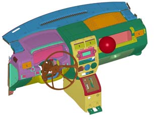 Figure 3. The crash-test analysis calculates the head-impact zone.