

Latest News
July 1, 2004
By Joe Greco
This 13th installment of Desktop Engineering’s MCAD Up Close series takes a detailedlook at the sketching capabilities found in today’s MCAD programs. While we havecovered many types of modeling problems in the series, the fact remains that mostmodeling operations are based on sketching, so it’s time to give the subject itsdue.
View the table of other popular MCAD programs
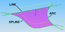
| Figure 1. This task was to draw an arc, line, and spline and see if the areaenclosed by them could be used for a modeling operation. |
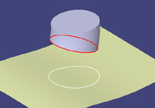
Figure 2. Most programs can project a sketch onto a nonplanar surface in orderto create a new sketch, so we looked at the ability to project an existing 3Dedge. |
|
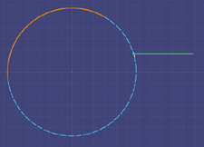
| Figure 3. As the highlighted horizontal line is drawn toward the arc, the arcis temporarily continued via the dashed line to show the user where it would meetthe line being created. |
With the help of MCAD users and vendors, we conjured up 20 conditions representingcommon problems that a typical designer incurs when sketching. We then dividedthem into six categories. The problems approximate difficult but practical conditions.At the same time, we decided they couldn’t be so difficult as to prevent me fromperforming each one in the eight programs I tested. Another one of our goals isto provide you with a good idea of the tools that should be included in a modernsketcher. That way, you’ll have some help choosing an MCAD program, even if itisn’t one of these applications.
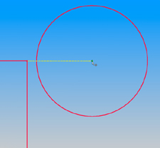
Figure 4. After the sketch elements are drawn, when moving them later on, theprogram should still make use of its inferencing capabilities to quickly alignobjects.
Creating/Editing Geometry- Line/arc Tool. All MCAD programs have lines, arcs, and other basic geometry,but a popular request made by users was the ability to easily switch between lineand arc mode while drawing a continuous segment
- Using existing 2D Geometry. I tested which products could select the negativearea between overlapping 2D entities and use it to construct models (see Figure1). Secondly, I also tested the snapping capabilities to key points located inother 2D sketches.
- Using existing 3D Geometry. First I projected 3D edges onto an existing nonplanarsurface in order to create a new sketch (see Figure 2). Then I also looked atthe ability to create a new sketch by offsetting existing 3D edges.
- Advanced Inferencing. This condition involves two criteria to help users aligngeometry by using temporary dashed lines. First, I was looking for inferencingbeyond what most programs offer, for instance, continuation of arcs (see Figure3). Second, I also checked to see if the inferencing worked when elements weremoved, not just when they were created (see Figure 4).
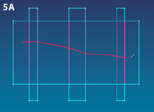
- Advanced Trimming Techniques. Trimming entities is something most programs takefor granted, but in my test scenario (see Figure 5), the amount of entities neededto be trimmed could result in a lot of clicking using traditional techniques.However, I checked to see if any program allowed this to be done in one shot,simply by dragging over the entities to be trimmed. Click here to see an animated representation of this feature.
- Smart Construction Geometry. Can the program make use of default workplanes andexisting geometry to mirror an object? Can the X axis and Y axis actually be usedas a reference for dimensions, which proves helpful when drawing symmetrical objects?
| Figure 5A, above, left: This image shows the objects that needed to be trimmed. |
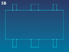
| Figure 5B (above, right). This image shows the trim result, achieved in essentiallyone step. Click here to see an animated representation. |
- Advanced Text Capabilities. Most sketchers have text capabilities for creatingembossments and so on. However, what I was looking for were advanced tools, onebeing the ability to drive text height as a parameter, for example, so an embossedlogo would always be 10 percent of the height of a bottle on which it was located.I also checked for the ability to add text on a curve.
- Tolerances. Do tolerances added during the sketching stage eventually get transferredto the final drawing?

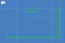
Figure 6A. (top): The notch needs to be centered. Figure 6B (below): The taskwas completed with one constraint and no dimensions; and the object’s overallsize remained the same. Click here to see an animated representation of this feature.
- Reposition Dimension. Is it possible to simply drag a dimension that was placedat the wrong point to a new position? Click here to see an animated representation of this feature.
- Drag to Override Dimension. Placing a dimensional constraint is important whensketching, but sometimes after placing it there is a need to change the objectit measures. So what we were looking for was a method to quickly and temporarilyoverride the dimensional constraint to allow the geometry to be changed.
- Advanced Constraints. Most programs have an Equal constraint, which allows oneentity to become the same size as another. But that doesn’t help when you wantto center a notch without increasing the size of the rectangle or adding a dimensionconstraint to the bottom edge of the object (see Figure 6). So a type of centerconstraint is what I looked for. A second criterion covered in this conditiondealt with the ability of the program to use its tangent constraint to createa cam-and-follower design.
- Interactive Constraint Toggle. Most MCAD programs assume that users automaticallywant constraints (relationships) to be added. Most of the time, this assumptionis correct; however, what if you want to draw a line that is parallel to anotherline, but you don’t want a parallel constraint to be added? So what I looked forwas the ability to easily turn off constraints while drawing; perhaps, for example,by holding down a special key.
|
Figure 7. This sample DWG file contained complex geometry, layers, dimensions,and text. |
- Different Formats. This is just a listing of the major bitmap formats that eachprogram is able to import directly into its sketcher, which is useful for tracingover a scan of a hand drawing.
- Bitmap Test. Importing a JPEG file into the sketcher of an MCAD program was frequentlyrequested. Whether the file could or could not be directly imported into the sketcher,I still tested to see if the scan could be repositioned and resized.
- DWG Test. We checked to see if the DWG file (see Figure 7) could be directlyimported into the sketchers of the MCAD programs. Then the three criteria I checkedfor were clean geometry (polylines, splines, etc., not broken), some sort of layercontrol, and dimensions and text that was still editable.
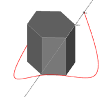
Figure 8 (above). The final point in this 3D spline is being placed at a locationin space that is aligned to the top edge of the 3D hexagon, as indicated by thedashed diagonal line.
3D Sketching and Referencing- 3D Snaps and Inferencing. When sketching 3D splines and arcs, was it possibleto snap to vertex points of existing 3D objects? Secondly, I checked to see ifinferencing worked with existing 3D objects (see Figure 8).
- Sketch on Surface. The ability to draw a sketch directly on a nonplanar 3D surfacewas tested.
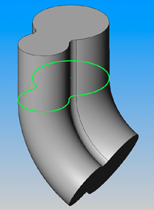
Figure 9. The sketch highlighted in green is basically doing double duty—it isthe profile of the extrusion as well as the profile for the revolve feature.
- Share Sketches. This topic came up many times with the users I spoke with. Anexample of this is when a single sketch is used to create multiple features (seeFigure 9). In addition, I looked at the ability to copy sketches to and from partsand assemblies.
- Layout Sketches. This is sometimes also called an assembly layout. It can beused, for instance, to show how sketched machine components are related to eachother. What I looked for was the ability to create sketches in the assembly modeand then relate them to each other either by constraints or formulas.
- Sketch Order. When editing the first of two sketches, can the second sketch stillbe viewed, even though it was created after the first one?
There are other sketching conditions that a designer might run across that Icouldn’t get to, but we hope this close-up of MCAD programs helps when evaluatingthe different programs that are available. Overall, most of the applications Ireviewed did well when tested for the problems I envisioned, but our best adviceis to use this article only as an initial guide, and perform your own testingand evaluation based on the sketching features that are important for your specificwork
Joe Greco is a Desktop Engineering contributing editor. You can send Joe your thoughtson this article c/o Desktop Engineering Feedback.
Autodesk, Inc.
415-507-5000
Dassault Systemes
818-999-2500
PTC - Parametric Technologies
781-370-5000
www.ptc.com
SolidWorks
800-693-9000
www.solidworks.com
think3
513-263-6777
www.think3.com
UGS Corp.
314-264-8000
www.ugs.com
UGS Corp. - Solid Edge
800-807-2200
www.solid-edge.com
VX Corp.
321-676-3222
www.vx.com
Subscribe to our FREE magazine, FREE email newsletters or both!
Latest News
About the Author
DE’s editors contribute news and new product announcements to Digital Engineering.
Press releases may be sent to them via [email protected].


