
Latest News
August 1, 2008
By Pamela J. Waterman
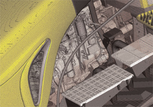 This engine-compartment closeup of an AGCO tractor shows that all of the detail of the original CADmodel is retained for a PowerFLOW simulation of airflow management and cooling. It wasnot necessary to defeature for the simulation and the volume mesh was automatically generated. Image courtesy of Exa and AGCO. |
If you remember anything from Finite Elements 101, it’s that successful design analysis includes creating a meaningful mesh. At a detailed level, analysts love to discuss the merits of shells versus solids and tet versus hex types. At the broader level, there are diverging approaches to the fundamental physics, and the needs of structural analysts differ from those analyzing fluid flow (meshing a surface/solid or the volume around it).
Defining the Problem
At COMSOL, Bernt Nilsson, senior VP of marketing, summarizes activity in the preprocessing arena. “The main challenge for the meshing community over the past years has been to develop tools that prepare the CAD model for efficient meshing. This includes both de-featuring operations that modify the underlying CAD model, often referred to as real operations, and tools for modifying an overlay topology on the original model, referred to as virtual operations.
“Both types of operations,” says Nilsson, “aim to remove small details such as fillets, short edges, and small or narrow faces that will either cause trouble in the mesh generation process or force an extreme mesh resolution near the small feature. By providing automatic or semi-automatic identification of small details, the preprocessor can save a large amount of time during preparation of the CAD geometry for analysis. The preprocessing efforts pay off by paving the way to get the most out of the finite element solvers in terms of speed and accuracy.”
Independent Expertise
In the realm of stand-alone meshers, three companies market products with years of development and improvements behind them: XYZ Scientific, Pointwise, and Siemens PLM Software. Each has strong opinions and technical differences, targets one or more different solvers, and develops extremely powerful products.
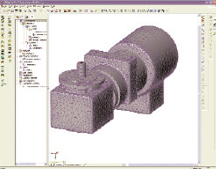 This motor model was meshed with NEiFusion using smart meshing that recognizes features for easy editing. Image courtesy of Noran Engineering. |
If you relish a great discussion of tet versus hex elements, talk to Robert Rainsberger, president of XYZ Scientific, developer of Truegrid. “Many companies typically rely on the easy methods: automatic tetrahedral mesh-generation for solids, and automatic triangular mesh-generation for shells,” he says. “With shell-mesh generation for sheets and thin objects, it’s not as big of an issue, but when it comes to solids, the differences between hex and tetrahedral are profound.”
Rainsberger says it boils down to whether people want to pay the price for hexahedral or whether tetrahedral is good enough. Areas where hex is very important include applications such as nonlinear, dynamic, and contact surface situations. As for automating the task of creating a hex mesh, he says, “It can be done, but it’s a much more difficult problem. That’s the holy grail of mesh generation.”
Compared to a structural analysis, where most of the elements are generally the same size, with fluids you might need a fine grid on a boundary where there’s turbulence and larger elements to efficiently describe volume as you move away from boundaries. Pointwise has always focused on this challenge, and is currently transitioning its long-time computational fluid dynamics meshing product Gridgen to the next generation, simply called Pointwise. The latter now offers a modern, intuitive graphical interface, undo & redo functions, and automated, fault-tolerant mesh assembly.
Rick Matus, Pointwise’s vice president of sales and marketing, says that his company’s typical users either want more control over the meshing task, or prefer to learn one mesher that works with multiple solvers. Targeted at the challenging needs of CFD analysts, Pointwise software offers a high level of user control for creating hex, tet, and hybrid grids, tackling complex geometry and very nonlinear flows where less-than-optimal meshing would translate into large differences in the analysis results.
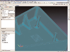 | 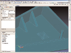 |
| These before (left) and after (right) images of a housing show where Femap software removed geometric details such as ribs, fillets, and stand-offs, andmerged surfaces together to simplify meshing. The job was done quickly using Siemens interactive feature-suppression tools within Femap. Image courtesy of Siemens PLMSoftware. | |
Siemens PLM Software has recently announced Version 10 of its Femap preprocessor, part of the company’s Velocity series. Tightly integrated with Nastran solvers with options for Abaqus, Marc, and LS-Dyna, version 10 introduces a set of interactive meshing tools for both surface and solid meshes so users can change mesh density by moving individual nodes or selected node sets, and see color-coded effects on the fly that check for element distortion based on customized quality criteria.
Femap lets you look at the mesh step by step. Among new features, you can see the detail and correct an area, mix beam elements with tet elements, and burn in surfaces around areas of high stress such as holes and fillets.
Broadening the Meshing Options
“Proper meshing is critical,” says Dave Weinberg, president of Noran Engineering. “A bad mesh can mean bad results, slow performance, and convergence issues in advanced analyses ]such as] nonlinear and eigenvalue extraction.” In describing a number of important areas for improvement, he lists smart meshing, which recognizes features and areas where stresses will be higher, and therefore adds more elements; interactive meshing that allows users to graphically select and edit elements and regions; mid-surface extraction for more accurate representation of thick regions; and CAD integration, where a change to the geometry triggers an automatic re-meshing.
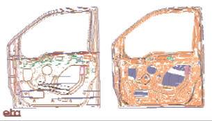 A sheet-metal and FE model of an automotive door assembly created with ETA’s VPG program with shell elements. The multiple panels in the door assembly were automatically welded during the meshing process. Image courtesy of Cranes Software. |
Noran offers its own meshing functions within NEiWorks and NEiFusion, where the FEA tasks are largely geared to concept viability, design modifications, and fabrication processes. The company bundles Femap with its own NEiNastran solver. Features include control over mesh size and sensitivity, and the repair and editing of CAD geometry. NEiNastran also offers Automated Surface Contact Generation and Automated Edge Contact Generation that allow separate meshing of components, mid-surfaced models, and off-set welds, then combine the meshes via proximity and user-defined settings.
High-end meshing functions are also part of the strategy behind Siemens PLM Software’s new Synchronous Technology, which refers to an intuitive direct-modeling technology described as history-free and feature-based. It has been incorporated in the NX 6 version of its advanced analysis software.
According to Richard Bush, marketing director for the Siemens Digital Lifecycle Simulation group, “This will make a huge difference for FEA analysts who, for example, will for the first time be able to take solid geometry from multiple CAD systems and make rapid changes.” The company expects to provide users with up to a 100-times faster design experience than before.
Is There a CAD Doctor in the House? Today’s meshers are getting much more sophisticated at streamlining geometry for faster preprocessing and solving, but one independent product that offers analysts guidance for geometry repair is CADdoctor from Elysium. CADdoctor supports all the standard CAD packages as well as IGES, ACIS, Parasolid, and STL formats, and has worked in a 64-bit format for years. Another offering is TransMagic Repair from TransMagic. Its latest version introduces parallel processing technology, a new JT read/write add-on translator, and major CAD version support. -PJW |
NX Advanced Finite Element Modeling (FEM) software uses Synchronous Technology to allow meshing and editing geometry even when there is no model history available. Its users can edit true features within the mesher, even on a “dumb” CAD file. Moreover, entire assemblies can be combined from different CAD modelers, and still be automatically meshed together.
More Automation, More Choices, Too
“In the old days, it often took more time to build the mesh than run the model,” says Vipul Kinariwala, head of business development for Cranes Software. “Now, with automeshers, we’ve cut that time by 80 percent.” Other improvements include running meshers on the original CAD geometry instead of recreating it, pre-treating the geometry to heal it, and taking advantage of multiprocessor and multicore computer systems.
Kinariwala, whose company markets NISA analysis software, points out that the quality of surface meshing has improved to the point where you can join multiple parts and surfaces, modeling welded and joined parts. He notes that sending separate parts out for simultaneous meshing on a parallel-processing system before bringing the meshes together will eventually save much time. (See Meshes by the Batch, above).
At SIMULIA, Abaqus/CAE serves as a high-end preprocessor for the Abaqus Standard and Explicit solvers. Asif Khan, Abaqus/CAE product manager, says, “In version 6.7, we focused on hex-meshing and bricks, including adding bottom-up hex-meshing where you could do increments (for highly curved areas). In version 6.8, the focus was on making tetrahedral meshes on complex parts.”
A major new function in Abaqus/CAE 6.8 is Automatic Virtual Topology, which makes it much easier to generate tet meshes. Where the geometry has fine features such as sharp corners or fine slivers, you can now specify values that define, say, short edges. The software highlights the areas with these parameters, allows you to accept them or not, then automatically creates “virtual features” that bypass the problem areas without distortion.
Other enhancements include element quality checks in real-time during the meshing, mesh seeding for optimizing mesh density, and adaptive remeshing (automatic and manual) to adjust the mesh iteratively after running an Abaqus Standard analysis.
“Within STAR-CCM+, CD-adapco has developed and implemented some of the fastest and most automated meshing on the market today,” says company VP of Marketing and Business Development Dennis Nagy. Nagy points out that dealing with the consequences of “dirty” or complicated CAD data has long been the biggest bottleneck in the CAE process and, until recently, was the single largest obstacle preventing automated meshing and the routine implementation of numerical simulation early in the design process.
| Meshes by the Batch Batch meshing is a term used to describe an approach to automatically make the mesh connections of multiple parts. One common example where that is highly desirable is with sheet metal for automotive and aeronautical applications. Specialized meshing packages exist for this purpose, such as ANSA for Batch Meshing from BETA CAE Systems USA, Hypermesh from Altair, and the VirtualPaintShop CATIA Toolkit from CADFEM, but the major general-purpose packages also have options for this task. -PJW |
STAR-CCM+, however, includes a geometry cleanup application called Surface Wrapping to fix the gaps, overlaps, and other typical problems involved in large assemblies of complex CAD parts. “It works by ‘shrink-wrapping’ a high-quality triangulated surface mesh onto the geometry,” says Nagy, “closing holes in the geometry and joining disconnected and overlapping surfaces. For CFD simulations, the Surface Wrapper quickly calculates the wetted surface of the geometry, automatically discarding surfaces that are outside the calculation domain, instantly eliminating unnecessary detail.”
The automatic meshing technology then generates either polyhedral or predominantly hexahedral control volumes at the touch of a button, offering speed, control, and accuracy. For problems involving multiple frames of reference, fluid-structure interaction, and conjugate heat transfer, STAR-CCM+ can automatically create conformal meshes across multiple physical domains.
For some companies, meshing has become such an automated part of the CAD-to-analysis flow that the fundamental marketing has changed.
“We don’t even have a separate meshing product line any more,” says Algor Product Manager Bob Williams. “It’s not really as involved as it used to be. Where you used to have people doing nothing but meshing, and ]others] doing nothing but analysis, it can all be the same person.” Williams adds that the most drastic change is the emphasis on taking geometry directly from CAD into analysis, rather than recreating the models within an FEA package.
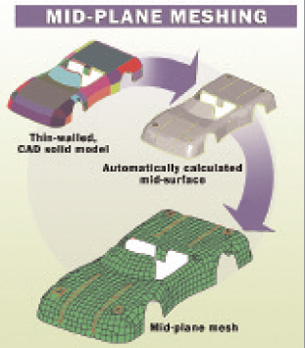 This image shows the the different stages of mid-plane meshing of plate or shell elements with an associated thickness as performed in ALGOR FEA software. Image courtesy of Core Tech System. |
“We’re trying to make this as seamless as possible,” he says. “We’ve automated a lot of what the user used to have to do manually.” For example, the software can apply a mix of element types. Users then run a mesh-size sensitivity test and see a comparison plot of the effects instead of trying five different mesh sizes manually.
Other Algor enhancements, particularly important for analyzing models with large nonlinear deformations, include the ability to mesh at mid-planes and add nodes at mid-edges of elements, but even that just requires a simple click.
Cutting Out The Middle Steps
“Instead of meshing the geometry ]itself] we provide meshing rules,” says MSC.Software CTO Reza Sadeghi, explaining his company’s SimXpert CAE solution no longer needs to translate a CAD model. “For example…we don’t turn the geometry into nodes and elements and forget the surface — we continue to build the model with parameters that would eventually turn that geometry into a mesh (surface, solid, or special elements).”
The analyst can now continue to interact with the system geometry until the model is ready to be converted to a continuum of finite elements for analysis. The Sim suite also has adaptive meshing algorithms and, as an option, the solver can enhance the mesh locally or globally based on user specifications. Global remeshing in SimXpert is a critical tool for handling nonlinear problems such as the stress in a rubber seal as it deforms. After an analysis, users have the bidirectional capability of mapping back to the original CAD surface. Sadeghi adds that the next step will be to perform similar tasks on NURBS entities.
Paying attention to the physics is a key strength in the broad line of ANSYS analysis products. Ben Klinkhammer, senior product manager, explains: “If I apply a boundary condition, where it indicates where a high stress concentration will be, we can key off that and use it as a meshing source control. We’re not quite there (overall), but when you’re setting up the model, you can optionally have the software apply some of these controls automatically.”
For structural analysis applications, Klinkhammer says analysts have always been good at de-featuring a model. More recently, they’re using the same kind of tools to create a more automated, parametric CFD model, too, for running multiple iterations. The thought is to now extend CFD capabilities to designer-level users.
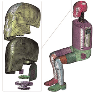 This model of a side-impact crash-dummy assembly shows the detail possible when hex-meshing with Truegrid. Image courtesy of XYZ Scientific. |
While the rest of the industry has been busy working with geometry repair and advanced element shaping, Exa Corp. has taken a different path since its inception.
“Everybody else starts with a surface mesh (on the part model) and grows the fluid mesh,” says Exa VP of Product Management Alex Mackenzie. “We do something completely different.” PowerFLOW automatically generates volumetric, cube-based grids (with elements called voxels) filling the fluid domain of interest, and then literally subtracts the shape of the immersed solid by using the solid and surface mesh model to “slice” through the cubes.
In its PowerFLOW line of products, the company uses immersive grid technology that successfully meshes parts within an assembly even if they overlap. With Exa’s patented Lattice-Boltzmann technique for solving the fluid flow there is also no need to simplify the product geometry to reduce the number of mesh elements, a process that often takes days or even weeks.
But Wait, There’s More
This article barely uncovers the capabilities and nuances available with today’s preprocessing software. For example, Altair’s HyperWorks offers extensive meshing options, from interactive surface meshing as geometry topology is changed, to “shrink-wrap” meshing that can intelligently mesh over gaps and holes. (For more geometry cleanup ideas, see “Is there a CAD Doctor in the House?” page 32).
Meshing Reources Subscribe to our FREE magazine, FREE email newsletters or both!
Join over 90,000 engineering professionals who get fresh engineering news as soon as it is published.
Latest NewsProduct Development Teams Feeling the Need for Speed
Sony, Siemens Enable Immersive Engineering with Jointly Created System
Siemens Unleashes Cloud-based 3D CAD/Engineering with NX X
SprutCAM X Updates Feature Robots
Linux Foundation Announces High-Performance Software Foundation
RAPID + TCT 2024 Executive Keynote Series Announced
All posts
About the AuthorPamela Waterman worked as Digital Engineering’s contributing editor for two decades. Contact her via .(JavaScript must be enabled to view this email address). Follow DE#8485
New & Noteworthy 
New & Noteworthy: Safe, Cost-Effective Metal 3D Printing - Anywhere
Desktop Metal’s Studio System offers turnkey metal printing for prototypes and...
New & Noteworthy: Direct Neutronics Analysis on CAD
Coreform Cubit 2023.11 workflows enable neutronics directly on CAD for next-generation nuclear energy...

New & Noteworthy: Agile Engineering Collaboration
Authentise Threads is a new software tool for distributed communications and project...

New & Noteworthy Product Introduction: Enterprise VR Headset
Lenovo ThinkReality VRX has an immersive display works with virtual, augmented and...
|