Helping design and engineering professionals discover, evaluate and specify technologies and processes that shorten the design cycle and enable success.

May 2026 Special Focus: Artificial Intelligence in Design and Simulation
In this Special Focus Issue, learn about the latest developments in the integration of artificial intelligence into engineering workflows.

Design & Simulation Software Guide 2025
In this Special Issue, Digital Engineering presents its second annual guide to design and simulation software vendors.
Two examples from MKS Instruments show how the program reveals unknown effects in process instrumentation.
Modeling with COMSOL Multiphysics has become an integral part of the design process in the advanced technology group at MKS Instruments of Wilmington, Massachusetts. The following two examples-one of a next-generation pressure rate-of-rise device, and the other of a throttle valve used in chemical vapor deposition processes-show how researchers and engineers have used this modeling software to expedite product development.
In new-product and technology development, the first step is to analyze and optimize a basic concept. When working with modeling software, we can quickly obtain initial results by reducing the problem to a 1D model, with which we can often understand a process' underlying physics. An attractive feature of COMSOL Multiphysics is its ability to solve 1D problems, which reduces the debug time to practically zero when we extend a model to 2D or 3D.
These techniques proved valuable in modeling a next-generation pressure rate-of-rise device. Often used in semiconductor manufacturing, such devices measure the rate of change of pressure in a fixed volume, and this parameter is related to the flow rate into the volume. Our latest model is the pMFV (mass-flow verifier), a compact diagnostic instrument that provides in-situ verification of mass-flow controller (MFC) performance. This next-generation MFC includes technology improvements to help users in semiconductor and high-purity thin-film applications increase tool throughput. It features real-time accurate flow control that is insensitive to upstream and downstream pressure disturbances. Toward that end, it runs advanced digital algorithms on an embedded processor and thereby achieves accuracy significantly improved over conventional PID-based digital MFCs.
Indeed, mass-flow verifiers traditionally have not considered the temperature rise of the gas inside the volume during a verification, so rate-of-rise devices can be off by as much as 10 percent. Modeling and then creating a device that takes this effect into account involved solving the time-dependent compressible Navier-Stokes equations in 3D.
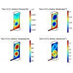 |
ۼ ۼ Figure 1: COMSOL Multiphysics plots of pressure (upper left), density (upper right), temperature (lower left), and velocity (lower right) inside the pMFV rate-of-rise instrument are shown at a flow rate of 2000 sccm (standard centimeters cubed per minute) of nitrogen. The simulation shows that at higher flow rates, two large vortices form inside the dead volume, and pockets of hot gas become trapped inside. By capturing this temperature increase in real time, it is possible to substantially increase device accuracy.
The ultimate goal of this project was to implement these equations in an embedded processor so they could run in real time on the pMFV, a task we handled with MATLAB (see sidebar, "Navier-Stokes in Real Time" below). We then needed to gain confidence that the numerics in the embedded code were accurate, so we compared results for the temperature dynamics in the volume from the real-time model, which uses the condensed equations, to the full 3D COMSOL Multiphysics model, which works with the full Navier-Stokes equations.
A prerequisite step was to collect experimental data, which we did with the MATLAB Data Acquisition Toolbox and PC-based digitizing hardware. By taking this approach, all the experimental data was immediately available in MATLAB format, so it was easy to plot pressure versus time in MATLAB and superimpose a similar plot calculated in COMSOL. We were pleased to see that the agreement between the COMSOL Multiphysics model and the experimental data is better than 99 percent for a wide range of gases and flow rates. In other words, our real-time model now executes on the shipping instrument to achieve a flow reading accurate to 1 percent of set point for all gases.
In the process we also gained further valuable knowledge. Specifically, when examining results from COMSOL Multiphysics simulations, we were surprised to see that pockets of gas inside the volume can increase by as much as 100 degrees C at high flow rates (see Figure 1, above). COMSOL Multiphysics was instrumental in helping us understand how this temperature increase affects the reported flow rate.
Another area where we found COMSOL Multiphysics quite useful was in the design of a throttle valve used in chemical vapor deposition (CVD). CVD is a process by which very thin layers of chemicals are deposited on a given surface, called the substrate, which is usually a large single crystal of a material such as silicon or quartz. The substance to be deposited, called the precursor, enters a CVD chamber in a gaseous state, often by means of a carrier gas that is not to be deposited.
Precursors supplied with a carrier gas can often be liquids at room temperature and pressure. Further, the precursor's vapor pressure at process temperatures can be as low as several torr (the torr is the standard measure of pressure in the semiconductor industry; 1 torr = 1mm Hg, and 760 torr = 1 atmosphere = 101.325 kilopascal). The market is moving toward precursors that have lower vapor pressures, and this trend brings with it a new set of design challenges we could adequately evaluate and overcome with the help of modeling with COMSOL.;)
;)
In a simulation of a throttle valve (left), COMSOL Multiphysics plots pressure (surface plot) and the velocity field (streamlines) across the valve flapper (right). The sudden drop in pressure and resulting expansion of the gas leads to a drop in temperature and an increase in local partial pressure of precursors. Condensation of the precursor can occur and cause clogging of the valve.
One of the key parameters in a CVD process is the pressure in the reactor, which is controlled with a throttle valve (see Figure 2, page 30). The valve chokes off the flow so that a considerable pressure difference can exist on different sides of the valve-it can be as high as 10 torr in the process chamber upstream of the valve compared to only several hundred millitorr downstream. Such a dramatic pressure drop in a distance of just millimeters can lead to a significant drop in the temperature of the carrier gas (see Figure 2, above). In addition, a vortex can form downstream of the valve because its opening is not exactly symmetric, so the flow area is larger on one side than the other. The vortex, in turn, leads to an increase in the local partial pressure of any precursor.
If the process does not use all the precursor, problems can potentially arise. In detail, the pressure drop and the vortex can both result in a drop in the temperature that causes the remaining precursor to condense. That condensate can cause process contamination and clog the valve over time. Before our COMSOL Multiphysics study, engineers were unable to explain why the condensate was forming, but with the model we can see these effects and take appropriate countermeasures.
Using the COMSOL Chemical Engineering Module we were able to draw these conclusions using two application modes: Non-isothermal Flow, Convection, and Conduction and also Convection/Diffusion. The most difficult part of the simulation was resolving the shock downstream of the valve blade. Streamline diffusion and a high mesh density were necessary to accurately resolve the shock and thus observe the large resulting temperature drop (see Figure 3, below right).
;)
ۼ ۼ Figure 3: A COMSOL Multiphysics postprocessing image of the throttle valve without the flapper reveals the dramatic temperature drop across the valve-it drops by 118 degrees C at the valve flapper and is a major contributor to condensation that can lead to poor valve performance over time.
The simulations clearly showed that heating the blade was not sufficient to prevent condensation, which results from the expansion of the carrier gas. Given this data, our engineers developed a novel way of eliminating this problem, a method we are now testing and plan to incorporate into future designs.
We will continue to use COMSOL Multiphysics to simulate and debug our designs. The ability to solve 1D problems and quickly evaluate a concept, freely manipulate the PDEs, and specify ODEs as boundary conditions give COMSOL Multiphysics a huge advantage compared to other FEA packages. We have been able to discover the cause of unwanted effects. In addition, once we have determined that a model agrees with experimental data, we can use it as a "noise-free" laboratory to further refine our designs.
Field measurements and experiments, by their very nature, always involve some amount of noise and uncertainty, but in a COMSOL Multiphysics simulation we can eliminate these effects and better study the basics behind new control algorithms and systems. Moving forward, the ability to solve large-displacement fluid/structure interaction problems with the ALE method in the latest version of COMSOL Multiphysics now allows us to simulate the dynamics of many of our existing and future products.
Ali Shajii Ph.D. is director of corporate advanced technology at MKS Instruments, a provider of materials delivery and reactive gas (plasma) equipment for the semiconductor industry. He earned his doctorate in engineering physics and applied math from MIT. He holds 18 U.S. patents and has written numerous technical articles. Daniel Smith is a staff scientist at MKS. He has masters degrees in applied mathematics from the University of St Andrews and in numerical computing from the University of Manchester. You can send an e-mail about this article by clicking here. Please reference "COMSOL Multiphysics, May 2006" in your message.
To run the Navier-Stokes equations on the MFV's embedded processor, we had to write them in C code. Here MATLAB played a major role
ۼ ۼ The Compressible Navier-Stokes equations are the foundation of all thermal fluid models. The third equation in this list is the energy equation, and the three terms on the right-hand side take into account compressional heating/expansive cooling and dissipative heating. These terms are easy to add to the convection/conduction application mode in the COMSOL Chemical Engineering module. .
We first developed the conceptual model using "back-of-the-envelope" calculations, then we first wrote a MATLAB script to implement and debug the control algorithm based on the equations. Next we condensed them into a simplified form to create a real-time model, and using MATLAB we converted it into C code that fits into the instrument processor's memory. Before committing the code to production models of the instrument, we compared experimental results with a COMSOL Multiphysics model to verify its accuracy.-AS & DS

DE's editors contribute news and new product announcements to Digital Engineering. Press releases may be sent to them via [email protected].
Follow DEJoin over 90,000 engineering professionals who get fresh engineering news as soon as it is published.


About Us · Contact Us · Editorial Team · Advertising · Privacy Policy · Subscriber Services · © 2026 Digital Engineering 24/7 · Peerless Media
;)
;)