Helping design and engineering professionals discover, evaluate and specify technologies and processes that shorten the design cycle and enable success.
Alert!
Digital Engineering ceased publication on July 1, 2026. This website remains available as an archive of engineering content.
For inquiries or information, please email [email protected].

Receiver testing for MIPI standards has always been a challenge for engineers and test equipment manufacturers. Fortunately, as technologies have evolved, the choice of test and measurement equipment has expanded to keep pace.
The MIPI Alliance’s first PHY, D-PHY, has had wide industry adoption for about 10 years now. With D-PHY as the starting point, MIPI standards have continued to evolve with an emphasis on application based PHYs and providing more choices for the mobile community to implement PHYs based on consumer use cases and the market being served. For example, C-PHY is a choice for high-end cameras, while D-PHY is used for camera and display. M-PHY continues to drive storage applications, like UFS.
Along with adding new PHYs, MIPI has evolved its specifications over time to meet market needs for higher data rates, low power and increased performance. Today D-PHY operates up to 4.5Gbps compared to 500Mbps when it started 10 years ago. M-PHY runs all the way up to 11.6Gb/s and C-PHY goes up to 3GS/s.
As the specifications have evolved, so have the needs for testing them. Some of the typical test and measurement challenges that engineers are facing include increased complexity in physical setup, maintenance of the setup, inability to generate a variety of stresses and the ability to generate various encoded patterns, all with the exact amount of jitter each time. For MIPI receiver testing the use of arbitrary waveform generator (AWG) technology is gaining momentum, especially for D-PHY and C-PHY due to the cost and time savings afforded by AWGs.
While there are AWGs with sufficient performance readily available in the market, MIPI receiver test needs for D-PHY and C-PHY call for updates to the requirements in terms of signal or stress generation, putting specific constraints on AWGs. This is an area worth looking at more closely. These constraints include the following:
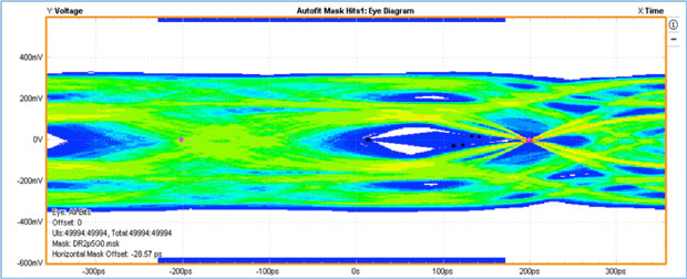 Fig. 1. Calibrated eye for C-PHY using the stresses as per the CTS. Image courtesy of Tektronix.
AWGs utilize direct synthesis methods for waveform generation and add different impairments with precise control, which is a challenge for many other types of generators. A few of the examples of signal generation and stresses required for D-PHY and C-PHY include spread spectrum clocking, dynamic skew, duty cycle distortion, ISI channel effects, de-emphasis, sinusoidal disturber signal, eSpike and more. The ability to generate de-emphasis, SSC, impairments such as DCD and skew, are recommended for calibration procedure for these PHYs as per the CTS. Figure 1 shows a screen capture of eSpike on a calibrated eye for C-PHY using the stresses as per the CTS. Figure 2 shows a calibrated D-PHY eye diagram.
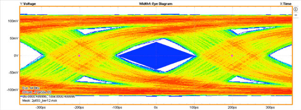 Fig. 2. Screen capture of a calibrated D-PHY eye diagram. Image courtesy of Tektronix.
An AWG provides much finer control, granularity and repeatability in terms of the signals and stresses being generated. It has the ability to generate a variety of different waveforms that support LP-HS transition for C-PHY and D-PHY, even with different startup sequences and sequencing on-the-fly. All these waveforms can also generate thousands of different test scenarios.
Additionally, the “sequencing” ability of the AWG allows you to sweep through a wide range of voltage values and stresses. It can generate multiple waveforms and sequence them so that they emulate the effect of turning the knob to dial in jitter. With the help of AWGs, it’s possible to save all these waveforms, use them offline and share them with teams globally. This helps with isolation of bugs early in the development cycle for globally dispersed teams.
There are ongoing discussions in the industry about even higher data rates for D-PHY and C-PHY. If these PHYs were to get close to M-PHY in terms of data rate, 11.6Gb/s, then the current AWGs available in the industry would fall short in terms of resolution and channel sample rate. Even a 6Gb/s D-PHY would require a channel sample rate of 25Gb/s per channel of output from a single channel of the AWG.
For C-PHY and D-PHY, the industry has moved from traditional generators to AWG-based testing. If enough thought is not put into the design of the new MIPI specs, we may have to move the industry to yet another instrument for future data rates. Industry experts need to have a holistic approach to designing the new specifications so that the existing test equipment can be reused and specifications evolved with consideration for the entire ecosystem.
However, if market needs lead to specifications with higher data rates, we may not have a choice but to explore new ways of redesigning existing equipment to meet the test and measurement needs of the industry or look at alternative equipment to enable new designs.
Keyur Diwan is a product marketing manager at Tektronix. Send email about this commentary to DE-Editorsmailto:[email protected].

Join over 90,000 engineering professionals who get fresh engineering news as soon as it is published.


About Us · Contact Us · Editorial Team · Advertising · Privacy Policy · Subscriber Services · © 2026 Digital Engineering 24/7 · Peerless Media