

Latest News
October 1, 2012
By Kenneth Wong
Author’s Note: A review of SolidThinking Inspire 9.0 is set to appear in a future issue. For a video demonstration of Evolve, click here.
Traditionally, engineering and design firms use digital simulation to verify and test their designs after the fact. By contrast, Altair Engineering, the company behind SolidThinking, and a few others believe simulation should be the guiding force even in early phases, in concept development. In what Altair calls “simulation-driven design,” idea exploration and geometry refinement go hand in hand: You sketch out an idea in 3D; you test its strength and function in simulation; you modify the design based on simulation results; then you test again.
Iterative process, by its very nature, demands swift, frequent changes to the design. This approach is often hampered by classic feature-based CAD modelers, which could be unforgiving if you attempt geometry changes that conflict with the steps you’ve taken to construct your design.Altair’s solution to this stumbling block is its own non-uniform rational basis spline (NURBS) modeler, SolidThinking Evolve. With a rich set of modeling tools to construct simple and complex surfaces, the software gives you a chance to break out of the mold of feature-based CAD. Because you work with spline curves in SolidThinking, you can get the flowing, swirly profiles not easily attainable in mechanical CAD programs. Perhaps most important, the software gives you a record of the steps you’ve taken to build your NURBS objects, so if you need to retrace your feature history for subsequent changes, you can.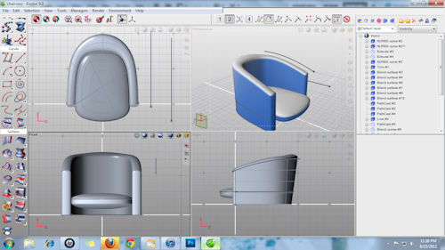 |
| The four-view setup in SolidThinking Evolve offers a way to observe your design changes and its effects from multiple perspectives. |
SolidThinking comes in two variations: SolidThinking Evolve, the modeling program; and SolidThinking Inspire, the simulation and optimization program. The latter is intended to help you identify the best shape, or the optimal form, that can satisfy your design requirements (pressure, stress, load and other anticipated conditions). Together, SolidThinking Evolve and Inspire make a powerful combo for the iterative process Altair envisions and advocates. This article focuses on Evolve 9.0. the latest version. A review of Inspire is set to follow soon.
General Interface
By default, SolidThinking Evolve launches with a four-view setup: top, front, right and perspective views. You may change the display mode in any of the views. You can, for instance, turn on zebra stripes in one view to check surface quality, wireframe in another to check edges and corners; and shading in another to see shadows and volume. The mix-and-match possibilities give you a way to observe your design in multiple modes simultaneously. Furthermore, as you refine the geometry in one view, corresponding changes occur in other views. So if you extrude the back of a chair in your perspective view, you see the effects of your changes in the top view and the side view as well. At any moment, you may turn one of the views into a full window to start detailed work.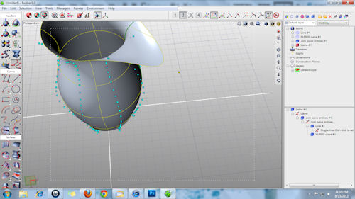 |
| By pulling and pushing on spline control points, you edit the underlying curve and the associated geometry (in this case, the volume of the vase). The windows in the far right offers the content of your scene (far right, top); and the historical steps involved in creating a feature (far right, bottom). |
The scrollable left pane gives you access to groups of tools: 2D sketching commands, surfacing commands, movement and translation commands (zoom, pan, scale, etc.), mesh tools, dimensioning tools and more. Once drawn, splines can be edited and modified through point handles. Both in 2D and 3D, the splines are extremely responsive to push-pull input, creating a stretchable feel to the models.
The far right corner gives you access to the world view, or the content of your scene. You can use this window to select the different components that make up your design, such as the spline you used to create the initial profile and the surfaces generated through extrusions and trimmings. Right below the world view, you get a list of the steps you took to create a specific feature: for example, a NURBS curve, followed by an extrusion. By selecting a specific step in the stack of operations, you may modify the outcome after the fact, by altering the underlying curve or the numeric input (say, the height of an extrusion) “similar to the way you would edit models in a feature-based CAD program’s history tree.Dimensions in Evolve can be static or associative. A static dimension is no more than a visual note of a value: say, the height of a vase. An associative dimension changes and updates when you alter your design. If you reduce the height of a vase by modifying its extrusion, the associative dimension will update to reflect the new height. But you cannot use a dimension edit to generate a geometry change. For instance, you cannot change the numeric value in the dimension from 3 to 2 in., and expect the height of the vase to automatically adjust itself. Such changes must be made from the world view by selecting the extruded object and modifying the extrusion input field.Surfaces and Splines
In addition to customary surface-creation methods (such as extruding a curve-enclosed profile), you may also use curves in other creative ways. With PathCast, you can project a curve onto another surface. Drawing a straight line or a simple arc on a flat surface is easy enough, but there will be occasions where you need to draw a curve on a complex surface with rolling angles. This is where PathCast can come in handy. Similarly, you may use curves to trim complex surfaces. When dealing with complex design, especially imported models, the Surface Extract tool gives you an easy way to identify a region, then generate a surface corresponding to this region.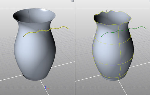 |
| Left: Setting up a trim operation using a spline to trim a surface. Right: Trimmed surface resulting from the operation. |
The power of a NURBS modeler is not only in how easy it is to create surfaces, but also in how good it is at automatically connecting adjacent surfaces in a logical fashion. When you use a command like Blend Surfaces in Evolve to join two (or more) surfaces, you’re bypassing the need to manually create an intermediary surface to fill the gap; instead, you’re relying on the software’s ability to detect the shapes of nearby surfaces and come up with a surface that connects them in an uninterrupted flow. SolidThinking works extremely well in blending surfaces in a way that preserves curvature continuity.
Editing Imported Designs
Evolve accepts imported files in neutral formats, such as IGES, STEP, OBJ, STL and DWG. However, the point-and-vertice editing style may prove a challenge in editing designs containing geometric symmetry. With point and vertice controls, it’s not easy to, for example, select a flat surface or an edge in an imported model to increase the thickness of a wall or the radius of a rounded corner. According to Darren Chilton, program manager for SolidThinking, Evolve’s companion piece Inspire 9.0 (in beta at press time) is expected to offer direct-modeling operations.Evolve comes with a rendering app, complete with panoramic environments, background plates and materials. With this option, you can instantly apply materials to your geometry, select a background, and produce a photorealistic image of your design, complete with shadows and reflective surfaces.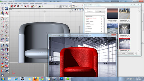 |
| The rendering tool in SolidThinking is preloaded with materials, environments and background plates. |
Evolve as a Companion to Inspire
In direct modeling CAD packages (such as Siemens PLM Software’s Solid Edge with Synchronous Technology, Autodesk Inventor Fusion, or PTC’s Creo Direct), you edit geometry by pushing and pulling on edges and surfaces. In a NURBS modeler like Evolve, you edit by pushing and pulling on points, vertices, meshes and polygons.The two approaches are significantly different. The first is a better choice for creating and editing clean, symmetrical geometry, made up primarily of perfect arcs, straight lines and rectangles (like an engine block or a desktop computer’s chassis). The latter is a better choice for constructing organic shapes with asymmetrical profiles and curves (like a leaf-shaped perfume bottle or the hood of a vehicle).On its own, SolidThinking Evolve is a powerful concept modeler. A generous collection of video tutorials that come with the installation reduces the learning curve to just a few hours to master the basics. Under Altair Engineering’s strategy, Evolve offers more value as a companion to SolidThinking Inspire, a program aimed at identifying optimal shapes. The optimization exercises in Inspire often reveal that the best shapes that satisfy the anticipated load in your design are not always a shapes you can arrive at intuitively. Though traditional CAD programs place an emphasis on creating symmetrical designs, and when most designers have, over time, developed a bias for symmetry in profiles, mathematical calculations may reveal that the best shape for a product is asymmetrical. (For more on this topic, read “The New Frontier in Digital Design: Automating Optimization,” Virtual Desktop blog, July 30, 2012.) This makes a NRUBS modeler like Evolve an ideal package for working with Inspire.Kenneth Wong is Desktop Engineering’s resident blogger and senior editor. Email him at [email protected] or share your thoughts on this article at deskeng.com/facebook.
More Info
Altair EngineeringSubscribe to our FREE magazine, FREE email newsletters or both!
Latest News
About the Author
Kenneth Wong is Digital Engineering’s resident blogger and senior editor. Email him at [email protected] or share your thoughts on this article at digitaleng.news/facebook.
Follow DE

