

Latest News
November 2, 2007
By Al Dean
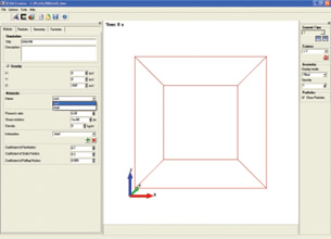 EDEM 1.3 is a particle-based simulation technology used for studying the mechanics of granular bulksystems yet offers wider application. The first step in using the program is defining your materials. |
To help fill this gap, DEM Solutions, based in Edinburgh, Scotland, has developed a discrete element modeling (DEM) application called EDEM, for the simulation, analysis, and visualization of particulate flow for providing “high-resolution information on particle kinematics, momentum, heat, and mass transfer.” But first, what exactly is DEM?
Discrete element modeling is a particle-based simulation technology that provides a numerical method of modeling the movement and contact between each particle in a physical system. A DEM model particle can represent either a single particle or group of particles. It is well established as a powerful tool for studying the mechanics of granular bulk systems and the process industries are rapidly expanding its use beyond the traditional areas of mining and geo-mechanics to pharmaceuticals, chemicals, oil, and gas.
DEM software tools, such as EDEM, can model both particles and equipment and provide a framework for investigating the relative effect of particle material properties, environmental conditions, and equipment design. Factors such as particle shape, surface properties (i.e., cohesion and electrostatic charge), temperature, and moisture content can be accounted for and particle-fluid flow can be modeled by co-simulation with CFD.
EDEM Creator: Steps
EDEM is an out-of-the-box commercial software that runs identically on both Windows and Linux (both 32-bit and 64-bit) and is split into three applications. The user interface is common across all three, which cover the preprocessing, solver, and postprocessing that most analysis users will be familiar with. So let’s run through the workflow and see what it can do.
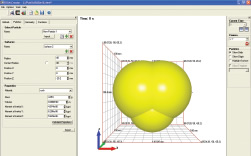 Particle types can be a simple sphere or built into more complex formsusing multiple spheres and a CAD file as a reference model. | 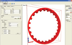 Geometry is imported using a wide range of industry-standard file formats,simplifying the process for users and reducing replication of effort. |
As with most simulation programs, the first task is to define the conditions and behavior. Within EDEM, this is done in four steps. The first is to define the global conditions with which you’re working — this includes standard properties such as gravity. You then need to define all of the materials, and because we’re dealing with the interaction between particles and other objects, you have a slightly different set of inputs than for traditional analysis. Alongside the normal density, you’ll need to set the shear modulus, coefficient of restitution, and coefficients of static friction as well as rolling friction.
Once your global setup is complete, the next step is to define the particles within your system. To optimize the process, EDEM uses a volumetrically accurate, user-definable description of a particle (and remember that when we’re discussing particles, you can model almost anything from nano-scale ingredients in the pharmaceutical industry to potatoes — yes, potatoes).
The basic particle form is a simple sphere, which ought to suffice in many instances. Should you want something more specific, you can use built-in modeling tools to create more descriptive particles using a series of spheres. Handily, you can load a CAD file and use that as a reference. You then calculate the properties such as mass, volume, moment of inertia, x, y, and z: many of these can be extracted from the model or loaded from an integral template.
The third step is to define the physical objects. The first is the domain, the work area as defined in terms of x, y, and z dimensions. This allows you to focus on the critical areas of what could be a very complex product or process. If you’re looking at mixing, it’s the tank and the blades. If you’re working on the loading conditions on a backhoe, then it’s the form of the bucket. This can be translated from your CAD models via IGES, STEP, Pro/ENGINEER, Fluent mesh file, Neutral, STL, ACIS, Parasolid, Ansys, CATIA V5 (CATpart and CATproduct). If you have moving components within your simulation job, you then define the movement. This can be done within EDEM, or you can link to a kinematic application such as Adams.
The final setup stage is the creation of Factories. Factories are the entities that produce the particles and introduce them into the simulation. Factories are dynamic or static in nature. You also define the nature of particles. What’s key to note is that because the system can simulate in excess of a million particles within a single simulation, you may choose to define variations of particle size and type using a number of methods. You also need to provide position, trajectory, velocity, and orientation of the particles as they are introduced into the simulation. While this might seem somewhat intimidating, the truth is that the whole process is highly graphical and — assuming that you have a solid understanding of the product, its operating conditions, and the process you’re looking to simulate — the entire setup process is very efficient.
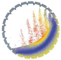 Here is an example of a mill with 100,000 particles.The mill was run at various rotational speeds to study particle-particle and particle-wall impacts as a function of mill speed and particle sizedistribution.Periodic boundaries are applied along the axis of the mill so only a slice is shown. |
EDEM Simulator
Next is calculation. Here, the system is again pretty self-explanatory. There are three tabs in the EDEM Simulator application. The first is Time and deals with setting up the period over which you want to run the simulation. You input the time step, the total runtime (i.e., the period of the time the simulation runs rather than the calculation time), then give it a write-out period. This is key to ensuring that you have a workable amount of data. By writing out the results at a specified value (in seconds), you can collect the amount of information you want without overextending the calculation time. The next tab is the Space tab. The domain in which you’re working needs to be split into a grid of cells to assist with calculating the interaction between the particles. These cells should be around the size of your particles. The final tab is where you set up the simulation run. Here you define the simulation contact model you’re using. The defaultHertz-Mindlin model covers a wide range of applications, but this can be substituted to cover specific requirements such as cohesion, conveyor belts, or electrostatics.
As ever, you finally hit run and leave the system running. The results can be viewed as they are calculated, allowing you to inspect the odd time step and see how things are looking as the system calculates how the particles and geometry are interacting. If something seems wrong, you can stop the analysis and rework some of the parameters without having to rebuild the entire model.
EDEM Analyst
The final application in the EDEM suite is EDEM Analyst, which provides the postprocessing or results inspection and visualization tools. You have full animation capabilities, so you can inspect the movement and interaction of your particles within the simulation and are offered coloring options to distinguish particles by any of their inherent attributes (velocity, force, inertia, etc.).
Of course, you’ll want to dive in and find greater detail than is available in a general overview of the simulation, so there are clipping planes and such. The Streaming tools let you display the path that individual particles take over the specific time frame, which is extremely useful for tracing movement within a system. For example, alongside simple movement, it can also assist with tracing particles from an end condition or position and then trace backward through time frames to find out where they originated. Such capability can assist in understanding and defining the key stages of any simulation. The greater sequenced insights provide a more detailed analysis for further investigation, if necessary.
While visualizing results is useful, for many, text export or charting tools are the most useful in terms of extracting relevant data. EDEM includes a full graphing suite that enables the creation of graphs and charts specifically tailored for representations. But should you need to, you can export directly to MATLAB and Excel.
Wider Use of DEM
Discrete element modeling is a new technology for most of us. To date, it has been used almost exclusively within several key application areas or industries, namely, pharmaceutical, chemical, and oil and gas as well as mineral and materials processing. These industries typically handle high-value processes where design optimization and development efficiency is key, but resolution of production issues is often mission critical and extremely costly. The fact remains, however, that particle simulation is applicable to a wider audience.
When you’re looking at any simulation process, there are assumptions that must be made, both to make the simulation process more efficient, and to work around the limitation of existing tools. Consider a good example — that of earth-moving equipment. If you use a static load on the bucket of a bulldozer using FEA techniques, that load is static, but the reality is that the earth the bucket passes through is dynamic in nature. Using FEA alone, you make a big assumption because that’s all the system can handle. But in DEM, you can simulate the movement of those particles and, in turn, the loading on your bucket will be more accurate.
EDEM is perhaps ahead of the game. While other DEM codes are out there, this is the first time I’ve seen a system that’s so focused on the mainstream. Yes, the parameters and variables you’re working with differ from more mainstream modeling tools, but the fact is that if you have a solid understanding of your product, process, or application, EDEM is eminently usable by anyone developing products where particles and their interactions are essential to the product’s performance. It interacts with other more traditional simulation tools, allowing you to transfer data between applications. The key to EDEM is that if used alone it enables you to simulate particle dynamics. Used in conjunction with other tools, it provides more accurate simulations that gather the information you need for better quality products, and that means one thing — competitive advantage.
More Information
DEM Solutions
Edinburgh, Scotland
dem-solutions.com
Al Dean is technology editor at MCAD Magazine, a UK product development and manufacturing technology journal (mcadonline.com) and is the editor of Prototype magazine (prototypemagazine.com). You can send comments about this article to DE-Editorsmailto:[email protected].
Subscribe to our FREE magazine, FREE email newsletters or both!
Latest News
About the Author
DE’s editors contribute news and new product announcements to Digital Engineering.
Press releases may be sent to them via [email protected].


