Helping design and engineering professionals discover, evaluate and specify technologies and processes that shorten the design cycle and enable success.

May 2026 Special Focus: Artificial Intelligence in Design and Simulation
In this Special Focus Issue, learn about the latest developments in the integration of artificial intelligence into engineering workflows.

Design & Simulation Software Guide 2025
In this Special Issue, Digital Engineering presents its second annual guide to design and simulation software vendors.
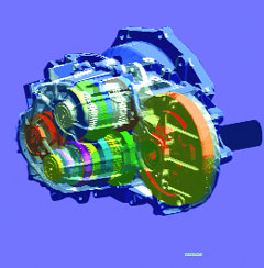
Above: The use of CAE methods to evaluate and understand gearbox noise in thedesign stage is reducing or eliminating the need for troubleshootingduring the prototype phase.
Move from Build and Test to CAE
For these reasons, Elasis, the Fiat-owned engineering company, starteddeveloping CAE methods to understand and evaluate gearbox noise in thedesign stage before prototypes are available. Over the last severalyears, the aim has been to assess the noise and vibration performanceof the transmission in the early design stages, optimizing the designwhile reducing or eliminating the need for troubleshooting during theprototype phase.
While this was going on, LMS International of Leuven, Belgium, washaving success focusing on the transmission housing, analyzing how itvibrates and radiates noise under known forces at the bearings, andthen determining how this noise is transmitted to the vehicle'sinterior. The transmission housing can be modeled using finite element(FE) and boundary element (BE) models, and the forces at the bearingcan be identified by means of experimental methods like Transfer PathAnalysis. The combined test-CAE simulation can be used to identifyweaknesses in the housing and make corrections by adding ribbing orchanging wall thickness.
This method can also be useful with current designs of gearboxes whenthere's one already available for testing, or when realistic forcesdefined from experience are applied to similar types of gearboxes. Andthis approach is appropriate when the noise problem lies in theresonance of the gearbox housing amplifying the internal forcesgenerated at the bearings. However, when the problem is mainly due tohigh excitation forces, the solution cannot always be found instructural housing modifications and another approach must be taken.
Eliminating Noise At Its Source
In its ongoing quest to make the entire development process moreefficient, Elasis decided to work with LMS International to simulategearbox noise generation mechanisms at the source using a detailed CAEmodel. The challenge was modeling the full complexity of the internaloperation of a new transmission to the level of detail required toaccurately predict internal dynamic forces in the wide frequency rangeassociated with gear rattle.
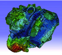
Above: LMS International has had success focusing on the transmission housingto analyze how it vibrates and radiates noise under known forces at itsbearings. Part of that analysis involves a finite element model asillustrated here.
LMS engineering specialists developed an approach that combinesmultibody simulation and BE analysis to capture the root causes ofnoise generation within the transmission. The first step wasaccomplished using LMS DADS software to create a dynamic model of theinternal mechanism incorporating gear stiffness, gear backlash, bearingcharacteristics, and hub and sleeve connection properties. Theflexibility of components like the gear shafts and housing arerepresented with modal parameters obtained from FE models. Engineersconsidered using a constant stiffness at the contact point of each pairof teeth because the focus was on gear rattle, so stiffnessfluctuations due to the moving contact between teeth was unimportant.
However, when focusing on gear whine it is possible to extend theprocedure, and engineers would not use the constant stiffness value.One can, for instance, use an analytical relationship that provides thestiffness of the tooth contact as a function of the parameters relatedto the contact location. This relationship can be incorporated into themodel as a user-defined subroutine.
The next step was building a BE model of the housing using LMS Sysnoisesoftware to predict the noise radiated under simulated conditions.
Validating the Accuracy of the Model
Elasis, which works on the Fiat-GM Powertrain joint venture carryingout research and development on vehicles and powertrains in addition toperforming other engineering chores for Fiat, decided experimentaltesting was necessary for validation at every phase of the modelingprocess. They used a state-of-the-art test rig built by Elasis toevaluate manual gearboxes. Within the scope of this project, the testrig was used to identify the main source of gear rattle and to providethe information and physical insights needed to validate the numericalmodeling and analysis.
Elasis calls this test rig a Virtual Engine Simulator (VES). It has theability to reproduce speed and torque fluctuations up to 500Hz, similarto those generated by an internal combustion engine minus the emissionsand space headaches. Moreover, it ensures that the gearbox is the solesource of the recorded noise, allowing for an in-depth study. Perhapsmost important, the VES allows the core parameters to be changed soengineers can perform parametric sensitivity studies.
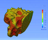
When multibody simulation is combined with a boundary element modellike this one, the root causes of transmission noise can be pinpointed.
One important new insight gained from testing showed that velocityfluctuations at the engine shaft primarily increased gear rattle at lowrotational speeds. Input to the multibody simulation includedcombustion pulsations represented by engine speed fluctuations, andresistance torque represented by the vehicle load. The multibodysimulation was carried out in fifth gear, with input (rotation speed)at the flywheel while applying a resistance torque at the transmissionoutput shaft. It turned out that the gearbox housing acted as the noiseradiator. Because it was simulated as a flexible componentcharacterized by the modes of an FE model, the modal participationfactors as a function of time were computed during the multibodysimulation. They were transferred to the frequency domain and appliedto the vibroacoustic model of the gearbox, which yielded the noiseradiation prediction. The simulated results were finally compared toactual physical measurements and clearly validated the modelingapproach.
This advanced modeling procedure can be used for optimization purposes,and a big advantage is that both the source parameters (gear clearance,contact stiffness, etc.) and the transfer path parameters (componentinertia and flexibility, housing dynamics, etc.) can be investigatedand modified to improve for both noise and vibration performance.
Mission Accomplished
This method will not only enable Elasis to make better design decisionsin the early phases of product development when prototype resultsaren't available, but it will also mean engineers can study far moredetailed information on design performance and the root causes of noiseproblems. This will lead to earlier evaluations of alternatives whencompared to the build-and-test method. And as the new simulationmethods are further refined and used more widely by Elasis, they shouldsubstantially improve the transmission design process, making itpossible to develop solutions earlier, faster, and cheaper.
Jerry Fireman is president of Structured Information of Lexington,Mass., a PR firm specializing in technology marketing. To reach Jerryabout this article, send an e-mail to [email protected].
Companies MentionedLMS International
Troy, MI
websiteElasis
Naples, Italy
website
Why Does My Baby Keep Whining?
Transmission designers have it tough. Now, more than ever, as road andengine noise have been greatly reduced, the clicks, hums, and clunksthat come from the tranny seem amplified. As a result, designers mustaddress noise problems that result from many different conditionsstemming from the clutch, gears, and all along the driveline. Inpractice, though, they can be divided into two major classes of gearboxnoise: whine and rattle.
Gear whine is a tonal noise that changes in relation to engine speedand the corresponding number of teeth in the different gear pairs. Itis caused by the fact that the rotational stiffness of the contactbetween two gear pairs varies as a function of time for two reasons.First, the number of teeth in contact varies through each revolution,alternating between two and three teeth gnashing together at any onepoint in time. Second, the point of contact between a given pair ofgears continually moves along the face of the teeth.
Consider each tooth a beam that is clamped at its root with its bendingstiffness changing as the contact point moves along its length. For onegiven tooth, that stiffness increases as the contact point moves towardthe root diameter and decreases as the contact point moves toward theouter diameter. This phenomenon also accounts for more variations inbending stiffness as a function of time.
The other source of noise, gear rattle, is a result of non-powertransmitting gears impinging upon other gears and shafts, resulting inmetal-to-metal impacts. These gears move within boundary limits definedby the tangential clearances between teeth of different gears and theradial and axial clearances between gear and shaft. These impact forcesgenerate a wideband vibration frequency and are driven by engine speedfluctuations.
Both gear whine and rattle forces are transferred to transmission shaftbearings, which in turn excite the transmission housing. And when thehousing vibrates, it acts as a noise radiator.—JF

DE's editors contribute news and new product announcements to Digital Engineering. Press releases may be sent to them via [email protected].
Follow DEJoin over 90,000 engineering professionals who get fresh engineering news as soon as it is published.


About Us · Contact Us · Editorial Team · Advertising · Privacy Policy · Subscriber Services · © 2026 Digital Engineering 24/7 · Peerless Media