Helping design and engineering professionals discover, evaluate and specify technologies and processes that shorten the design cycle and enable success.
In the early 1900s Henry Ford gathered best practices and ideas from unrelated industries such as meatpacking, Campbell's Soup, and Singer sewing machines (machines with interchangeable parts) to "invent" the assembly line. That he was the sole inventor of the assembly line is said to be a myth spread by marketers to enhance the Ford Motor Company's reputation. But Ford did, in fact, hire technical experts from these leading companies to implement his vision of the assembly line. The lesson here is that innovation is most always a joint activity that bridges distant industries and worlds.
 A recent book, How Breakthroughs Happen by Andrew Hargadon (Harvard Business School Press, 2003), outlines a process for innovation whereby designers leverage technology, people, and ideas to deliver breakthroughs. In the measurement industry such breakthroughs happen today, and the concept of virtual instrumentation (VI) is at the heart of the measurement innovation.
The VI innovation curve began in the late 1980s. It took concepts from diverse areas such as personal computers (the Apple—graphical user interface), software computing (Lotus 1, 2, 3—spreadsheet), and traditional instruments (Hewlett-Packard—oscilloscopes) to create a new vision for instrumentation. Today, using the PC, plug-in hardware, and off-the-shelf software such as Microsoft Visual Basic or NI's LabVIEW to create custom measurement systems is commonplace. With a forward-looking perspective, here are two recent innovations driving new capabilities for measurement, control, and VI.
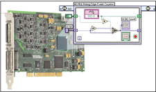
| Figure 1: The LabVIEW FPGA graphical user interface allows more engineers to leverage FPGA technology because its ease-of-use abrogates any requirement for deep programming expertise. |
The core architecture and technology for data acquisition (DA) hardware is in flux. Past designs used discrete components and specially designed, expensive ASICs (application-specific integrated circuits) to digitize and pass data to the PC. Designs today use FPGA (field programmable gate array) technology to package, process, control, and move data to the PC. FPGA technology is a source of renewed innovation and new capabilities for DA and VI. Driving these new capabilities is the capacity for a measurement and control application developer to program an onboard FPGA.
You can think of an FPGA as millions of logic gates that are not connected or programmed. Consumer electronics product designers use FPGAs in a broad range of high-volume products such as digital cameras; digital television, set-top boxes, and game console; PC screen projectors and graphics boards; and GPS driver information systems. Among the reasons product designers use FPGAs are processing speed, size, low power, and the ability to upgrade the core logic.
Parallel processing is a key stimulus driving designers of measurement and control devices to use FPGA. FPGAs can handle complex filtering, control loops, counter time, and serial digital operations all in parallel on independent I/O lines, whereas digitizers push data to the PC using a time-sliced single processor approach. In addition, an FPGA clock can run up to 80MHz, allowing engineers to run several simultaneous control loops on one FPGA at rates up to 12.5ns.
Another FPGA benefit is that the algorithms and code for measurement and control devices are field upgradable. However, up until recently, it has been relatively difficult for application developers in the lab or the manufacturing floor to take advantage of the ability to program FPGA devices. Typically, the DA hardware supplier delivered fixed control and analysis functionality in the FPGA. For example, several vendors offer plug-in devices with multiple ADCs (analog-to-digital converters) connected to an FPGA. The FPGA has predefined custom algorithms to implement a range of functions that could include a wideband receiver or FFT (fast Fourier transform) engine. Thus, users were locked into the functionality delivered by the vendor, and could neither modify nor create and deploy code to the FPGA.
Earlier generation software development tools were not user-friendly enough to enable engineers and scientists with little software programming expertise to easily implement a measurement and control system using FPGAs. A few years ago, the president of a leading supplier of FPGAs estimated that some day there could be as many as 100,000 FPGA programmers worldwide.
Today, that forecast may be an incredible underestimation. We could be at the beginning of an era of new performance, capabilities, and cost, all driven by measurement and control developers empowered to program FPGAs. Easy-to-use software tools such as LabVIEW FPGA, may spawn more FPGA programmers than anyone's expectations in the measurement and control industry alone (see Figure 1). These current innovations also extend VI even further by incorporating new features such as timed loops and a method for linking in FPGA IP Cores code from third parties like Xilinx that work on an assortment of analog and digital I/O boards for CompactPCI, PXI, and PCI.
A New Sensor— The Smart SensorSmart sensors are another breakthrough innovation. Core transducer technology for converting physical phenomena into a voltage for common measurements such as temperature, strain, and acceleration has been relatively unchanged for decades. The key innovations for sensor technology are driven by ideas taken from the desktop computer market. It was only a few years ago that connecting a peripheral to a sensor was relatively difficult. Desktop computers have become vastly simpler in last 10 years while connectivity for sensors has not changed much. A new standard for sensors, known as IEEE 1451.4, seeks to reduce the complexity and challenges associated with sensor connectivity, self-identification, and configuration.
IEEE 1451.4 defines a protocol to make sensors plug-and-play, similar to the way a USB mouse is plug-and-play with a computer, and it defines a mechanism for adding self-describing behavior to sensors with an analog signal interface. The concept shown in Figure 2 (below) uses the traditional analog signal combined with a low-cost serial digital link to access a Transducer Electronic Data Sheet (TEDS) embedded in the sensor. 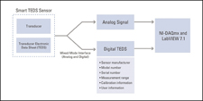
Figure 2: Smart sensors simplify connectivity, configuration, and maintenance of sensor information. This simplified chart depicts some of the categories of information available from TEDS technology.
Currently, configuring a DA system entails manually entering sensor parameters, such as range and sensitivity, from a printed data sheet. This information is used to mathematically convert raw voltages from the sensor into scaled engineering units. A system with smart TEDS sensors automates this process by reading sensor parameters digitally from the TEDS chip on the sensor. Thus, erroneous data entry is essentially eliminated.
Although other smart sensor technologies have been proposed, IEEE 1451.4 is unique because it uses the sensor's analog output. This feature makes smart TEDS sensors compatible with legacy sensors and DA systems. In addition to reducing the upgrade complexity, TEDS also make it easier for sensor manufacturers to add plug-and-play capabilities to their products: Dozens of sensor vendors, including Honeywell-Sensotec and Endevco, offer smart TEDS sensors already.
Since smart sensor products do not require manual sensor configuration, they can minimize system setup time. With a click of the mouse, measurement and control services software, such as NI-DAQmx 7.2, can automatically read the TEDS information of one or more smart sensors that are connected to the system. When plugged in, the sensor not only describes itself and its parameters to the system, it also indicates its physical channel connection. This characteristic simplifies asset management because you no longer need to track which data sheet corresponds to which sensor. Lost data sheets no longer means calling the sensor vendor for a printed replacement.
Smart sensor products can also maintain their own calibration schedules. Because TEDS include information about the sensor calibration date and period, smart sensors can tell the system when it needs recalibration.
Because the sensors describe themselves to the system, you do not have to track which sensor is connected to which channel. For example, you can connect 100 smart TEDS accelerometers in any order to 100 input channels. TEDS also provide a user-defined area to program information, such as the physical location of the sensor (i.e., "front-bearing housing, motor 1"). Regardless of the input channel, the DA system knows the physical location of the sensor.
The Future Is Here—It's Just Quiet About ItMeasurement and control developers are constantly embracing new technologies and ideas. Innovations are driving increased performance and ease-of-use to help solve unforeseen applications. To some degree, that unforeseen future of application development is here already…it is just unevenly distributed.
The challenge is finding or developing a network of people to make the future happen. And people—the last element of the innovation process described in Hargadon's book—are the wellspring from which flow the insights and innovations that will shape the future.
John Hanks serves as Hardware Platform Manager for National Instruments in Austin, TX. Send John your feedback on this c/o Desktop Engineering Feedback.
TEDS Resource OnlineTransducer Electronic Data Sheets (TEDS) enable your DA system to detect and automatically configure sensors. The promise of TEDS technology is that it will reduce configuration time by eliminating manual data entry, improve accuracy with detailed calibration information, and provide better reliability and simpler asset management.
This is all fine and dandy, but how do you leverage TEDS technology? And how can you get a couple to check out?
The answer to those questions and a lot of other stuff that you might not have thought of can be found on a dedicated page of TEDS information on the National Instruments website. There you can download a technology white paper on TEDS as well as access a 30-minute demonstration video of TEDS.
Additionally, the page offers you DAQ Designer, an online facilitator that, step-by-step, helps you build a data acquisition system to fit your requirements. You can also peruse a smart sensor product and company locator, print out company and product lists, or enter your desired sensor type with various specifications and find the specific sensor that meets your requirements. E-commerce capabilities are available on the spot.
To check out National Instruments's TEDS resource, go to www.ni.com/pnp. —DE
Company information

DE's editors contribute news and new product announcements to Digital Engineering. Press releases may be sent to them via [email protected].
Follow DEJoin over 90,000 engineering professionals who get fresh engineering news as soon as it is published.


About Us · Contact Us · Editorial Team · Advertising · Privacy Policy · Subscriber Services · © 2026 Digital Engineering 24/7 · Peerless Media